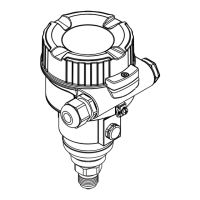
Gammapilot FMG50
18 Endress+Hauser
A0028908
3 Block diagram of HART connection
1 Device with HART communication
2 HART resistor
3 Power supply
The HART communication resistor of 250 Ω in the signal line is always necessary in the case of
a low-impedance power supply.
The voltage drop to be taken into account is:
Max. 6 V for 250 Ω communication resistor
Terminal assignment
A0038895
4 Connection terminals and ground terminal in the connection compartment
1 Internal ground terminal (to ground the cable shield)
2 Negative terminal
3 Positive terminal
• Non-Ex: supply voltage: 14 to 35 VDC
• Ex-i: supply voltage: 14 to 30 VDC
Cable entries
A0038156
1 Cable entry
2 Dummy plug
The number and type of cable entries depend on the device version ordered. The following are
possible:
• M20 threaded joint, plastic, IP66/68 NEMA Type 4X/6P
• M20 threaded joint, nickel-plated brass, IP66/68 NEMA Type 4X/6P
• M20 threaded joint, 316L, IP66/68 NEMA Type 4X/6P
• M20 thread, IP66/68 NEMA Type 4X/6P
• G1/2 thread, IP66/68 NEMA Type 4X/6P, with enclosed M20 to G1/2 adapter

 Loading...


