EPS-J6
PLUS Power Circuitry
POWER
SUPPLY
MEASUREMENTS
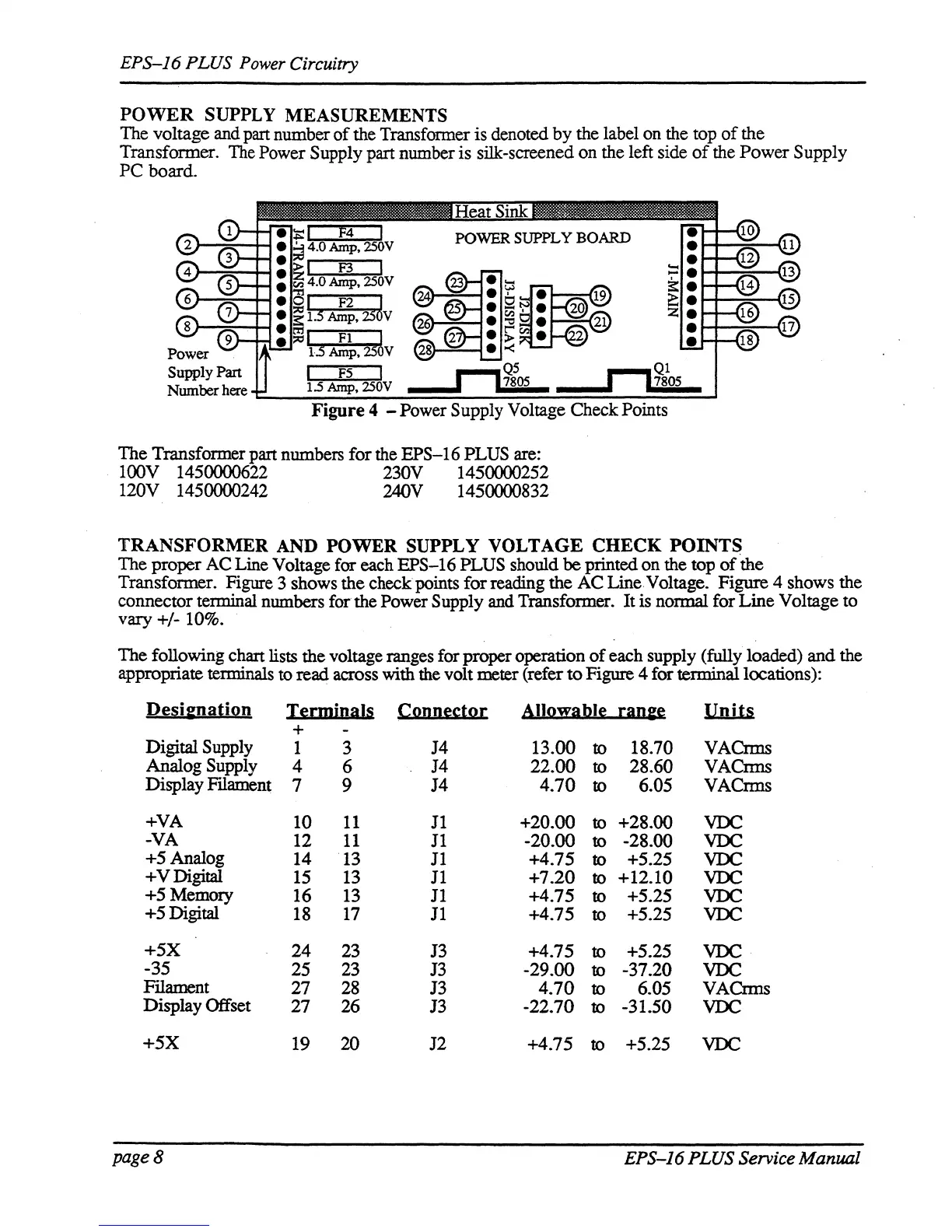
The voltage and part number
of
the Transfonner is denoted by the label on the top
of
the
Transformer.
The
Power Supply part number is silk-screened on the left side
of
the Power Supply
PC board.
I F2 J
1.5
Amp,
25
v
I
FI
~
dAmp,25 V
F5
The Transformer part numbers for the EPS-16 PLUS are:
100V 1450000622 230V 1450000252
120V 1450000242 240V 1450000832
TRANSFORMER
AND
POWER
SUPPLY
VOLTAGE
CHECK
POINTS
The proper AC Line Voltage for each EPS-16 PLUS should
be
printed on the top
of
the
Transformer. Figure 3 shows the checkpoints for reading the AC Line Voltage. Figure 4 shows the
connector terminal numbers for the Power
Supply and Transformer. It is normal for Line Voltage to
vary +/-
10%.
The following chart lists the voltage ranges for proper operation
of
each supply (fully loaded) and the
appropriate terminals
to
read across with the volt meter (refer
to
Figure 4 for terminal locations):
De~i&nali2n
I~rmiDals
CQDD~s:tQ[
AIIQ!fa.bI~
[aD&~
Units
+
Digital
Supply
1
3
J4
13.00
to
18.70 VACrms
Analog
Supply
4
6
J4 22.00
to
28.60
VACnns
Display
Fllament
7
9
J4
4.70
to
6.05 VACrms
+VA
10
11
J1
+20.00
to
+28.00
VDC
-VA
12
11
J1
-20.00
to
-28.00
VDC
+5 Analog
14
13
J1
+4.75
to
+5.25
VDC
+VDigital
15
13
11
+7.20
to
+12.10
VDC
+5 Memory
16
13
11
+4.75
to
+5.25
VDC
+5 Digital
18
17
11
+4.75
to
+5.25
VDC
+5X
24 23
13
+4.75
to
+5.25
VDC
-35
25 23
J3
-29.00
to
-37.20
VDC
FIlament
27 28
J3
4.70
to
6.05
VACnns
Display Offset
27 26
J3
-22.70
to
-31.50
VDC
+.5X
19 20 J2 +4.75
to +5.25
VDC
page 8
EPS-J6 PLUS Service Manual