Hardware Notes
EPS-16
PLUS
RACK
ONLY
1.
Dim
Displays
or
Extra
Segments (SIN 10000 to 10244)
On
early
EPS-16
PLUS
Racks, there is a potential for the Display to
shon
out
to
the
front panel.
This
can
cause extra segments
of
the display to light
or
the whole display
may
appear
dim.
To
fIx this problem, remove the keypad/display board from the front panel. Place insulating tape
along
the
flat inside
edge
of
the front panel (both top
and
bottom). Reinstall the KeypadlDisplay.
2. Panasonic m-257
Disk
Drive
On
early
EPS-16
PLUS Racks that have a Panasonic JU-257 disk drive, there is a potential for a
short between the
disk drive mounting bracket and the case
of
the disk drive that
may
cause audio
noise during a floppy disk access. There are two ways
to
fix
this problem:
• Place insulatiDg tape
on
the sides
of
the drive to isolate the
it
from the mounting bracket,
or
• Carefully remove (desolder) the surface-mounted resistor labeled
RI30
from
the
disk drive
PCB.
With the bezel closest
to
you
(pCB side up),
R130
is located
on
the
right
side
of
the
PCB
next to the
PCB
mounting screw.
3.
Main
Board
PEM
(threaded mounting standoff)
On
some
early units,
one
main
board screw was left
out
due
to
the misplacement
of
a Main Board
mounting
PEM.H
there is
no
screw
in
this location (see
Figure
11), don't insert one.
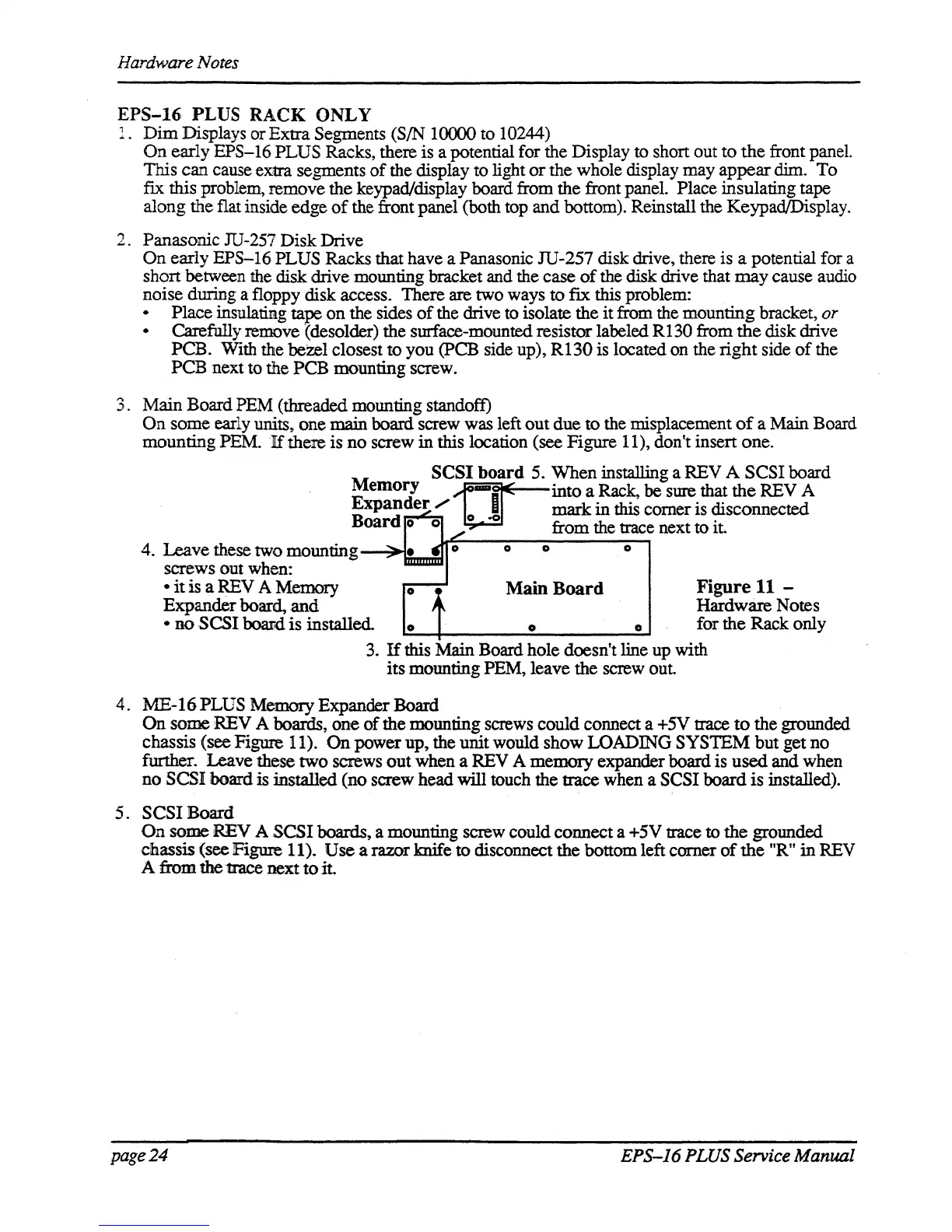
M
SCSI board 5.
When
installing a REV A
SCSI
board
emory
cr-
into
a Rack,
be
sure that
the
REV A
Expander.", 0
mark
in
this
comer
is disconnected
Board 0 0 0
-0
from
the trace next to it.
4.
Leave
these two mounting
screws out when:
o 0 0
•
it
is a
REV
A Memory
Expander
board,
and
• no SCSI bom:l
is
installed.
o
o
Main
Board
o 0
Figure
11
-
Hardware
Notes
for the Rack only
3.
If
this Main Board hole doesn't line up with
its
mounting PEM, leave the screw out.
4. ME-I6 PLUS Memory Expander Board
On
some
REV
A boards,
one
of
the mounting screws
could
connect a +5V trace
to
the grounded
chassis
(see Figure 11). On
power
up,
the unit would
show
LOADING
SYS1EM
but
get
no
further. Leave these
two
screws
out
when a
REV
A
memory
expander board is used and when
no
SCSI
board is installed
(no
screw head will touch the trace when a
SCSI
board
is
installed).
5.
SCSI
Board
On
some
REV
A
SCSI
boards, a mounting screw could connect a +5V trace
to
the
grounded
chassis
(see
Figure
11).
Use
a razor knife
to
disconnect
the
bottom left corner
of
the
"R"
in
REV
A
from.
thettace
next
to
it.
page
24
EPS-J6
PLUS Service Manual