Communications
Path
COMMUNICATIONS PATH
It
is
imponant
that you completely understand the communications
path
of
the
EPS-J6
PLUS.
Please read this carefully.
The
EPS-16
PLUS
Main Board, KeypadlDisplay Board
and
Keyboard assembly are complete
computer
systems in themselves, each with its
own
microprocessor and operating software. The
modules communicate with each other using serial communication
ports. Whenever a
key
is played
on
the Keyboard, for example, the Keyboard assembly microprocessor transmits this infonnation
to
the microprocessor on the Main Board.
The
KeypadlDisplay Board communicates with the Main Board through the Keyboard assembly.
Whenever
the Main Board wants to put a message on the Display,
it
sends the message
to
the
Keyboard
assembly which then passes
it
on
to the Display. Whenever a button is
pressed
on the
control panel, the
KeypadlDisplay Board sends the message to the Keyboard assembly which, in
turn,
passes
it
on to the Main Board.
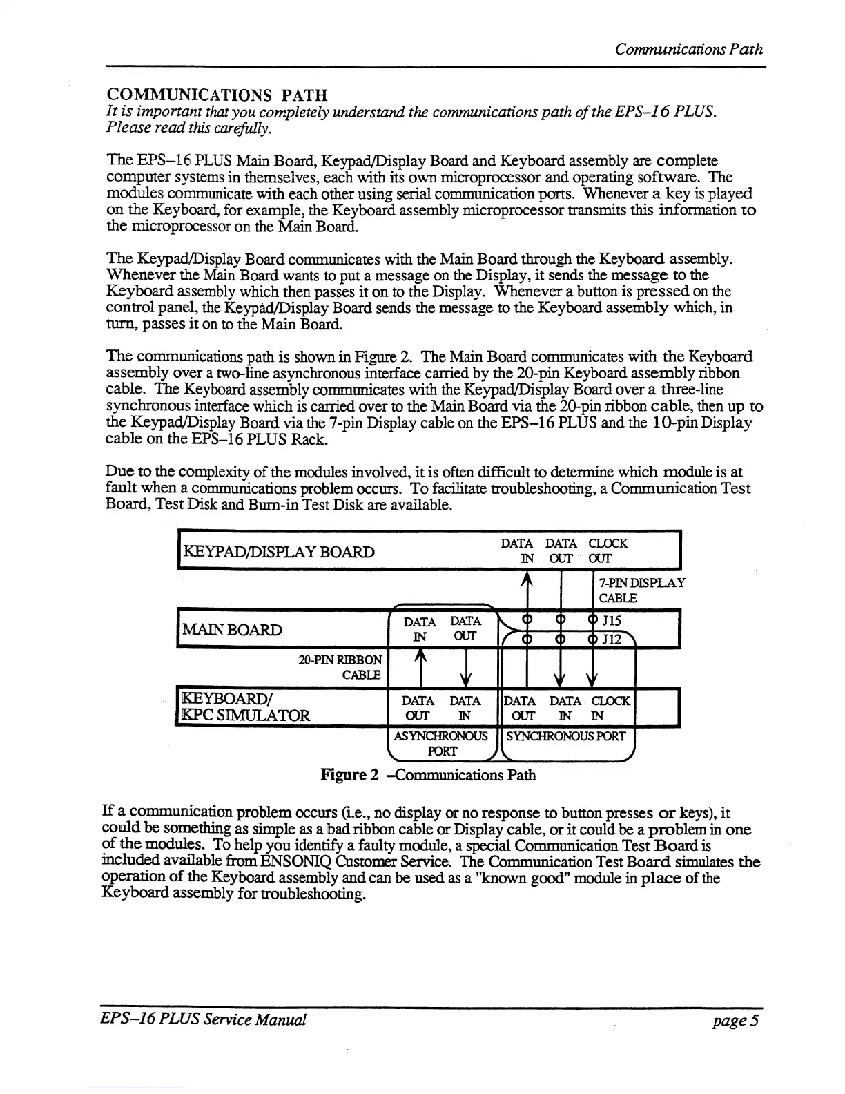
The
communications path
is
shown in Figure 2. The Main Board communicates with
the
Keyboard
assembly over a two-line asynchronous interface carried
by
the 20-pin Keyboard
assembly
ribbon
cable. 'The Keyboard assembly communicates with the Keypad/Display Board over a three-line
synchronous interface which is carried over to the
Main Board via the 20-pin ribbon
cable,
then
up
to
the Keypad/Display Board via the 7-pin Display cable on the
EPS-16
PLUS and the
10-pinDispiay
cable
on
the
EPS-16
PLUS Rack.
Due
to
the complexity
of
the modules involved,
it
is often difficult
to
detemrlne which module is
at
fault when a communications problem occurs.
To
facilitate troubleshooting, a Communication
Test
Board,
Test Disk and Bum-in Test Disk are available.
KEYPAD/DISPLA Y BOARD
DATA DATA
CLOCK
IN
our
our
J
7-PIN
DISPLAY
CABLE
MAIN BOARD
DATA
DATA
,0
()
0115
IN
our
C
4)
(~
112
2O-PIN
RIBBON
, ,
CABLE
,
,
\
KEYBOARD!
DATA
DATA
DATA
DATA
CLOCK.
,
KPC
SIMULATOR
our IN
our
IN IN
ASYNCHRONOUS
SYNCHRONOUS
PORT
FORT
~\..
~
Figure
2 -Communications Path
If
a communication problem occurs (i.e.,
no
display or no response
to
button presses
or
keys),
it
could
be something as simple as a
ibad
ribbon cable
or
Display cable,
or
it
could be a
problem
in
one
?f
the
modules. To help you identify a faulty module, a special Communication Test
Board
is
mcluded
available from ENSONIQ Customer Service. The Communication Test
Board
simulates
the
operation
of
the
Keyboard assembly and can be used
as
a "known good" module in
place
of
the
Keyboard
assembly for troubleshooting.
EPS-J6
PLUS
Service Manual
page 5