Connecting Stacking Cables
SecureStack A2 PoE Installation Guide 3-7
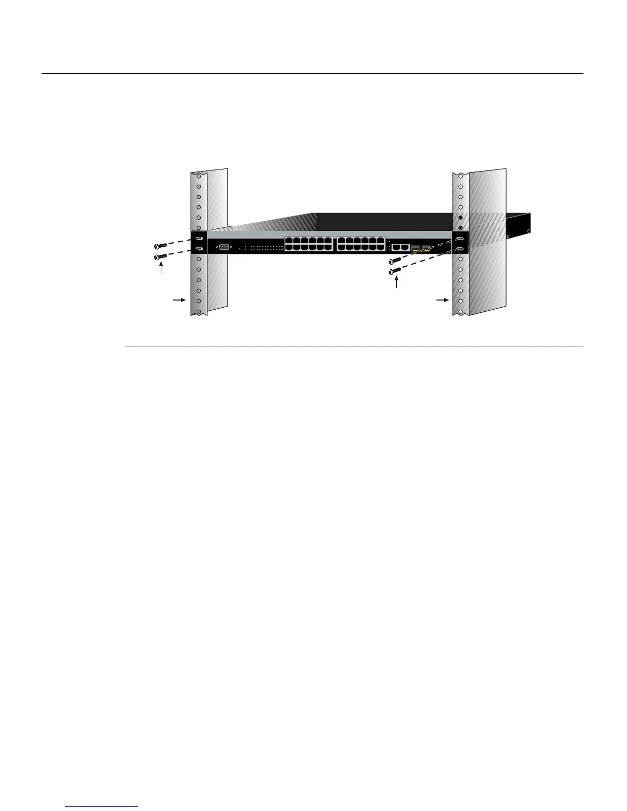
2. Withthemountingbracketsat tached,positiontheswitchbetweentheverticalframe
membersofthe19‐inchrackasshowninFigure 3‐4.Thenfastentheswitchsecurely
totheframeusingfourmountingscrews(usersupplied).
Figure 3-4 Fastening the Switch to the Rack
3. Ifyouareinstallingthisswitchinastackedconfiguration,repeatthisprocedure
for
eachswitchuntilallswitcheshavebeeninstalledinthestack,thenproceedto
“ConnectingStackingCables”onpage 3‐7.Otherwise,proceedto“ConnectingAC
andPoEPower”onpage 3‐12.
Connecting Stacking Cables
Thestackofswitchescanbeconnectedinaclosedloopordaisychained.Inaclosedloop
alltheswitchesareconnectedinsequenceandthelastswitchinthestackisconnected
backtothefirstswitch.Inthedaisychainconfigurationthecablethatwouldreturnthe
connection
backtothefirstswitchinaclosedloopisnotinstalled.Theadvantageofthe
closedloopisredundancy,thisconfiguration eliminatesanysinglepointoffailure.Upto
eightswitchescanbestackedtogetherandconnectedbystandardUTPCategory5or
bettercables.Youcanaddswitches
andreachuptoamaximumof384fixedfrontpanel
portsand16SFPportsforatotalof400Ethernetportsperstack.Thestackingcablesallow
theentirestacktooperatewithasingleIPaddress.
Figure 3‐5showsanexampleofafour‐highstackconnectedin
aclosedloop
configuration.AllSTACKDOWNandSTACKUPconnectorsareusedintheinstallation.
ThestackingcableconnectionsarefromtheSTACKDOWNconnectorofoneswitchto
theSTACKUPconnectorofthenextswitchupinthestack.Astackingcableconnection
fromtheSTACKDOWNconnector
oftheswitchatthetopofthestacktotheSTACKUP
connectoratthebottomofthestackclosestheloop.Inadaisychaintopology,onecable
connectionisnotmade.
1 Rails of 19-inch rack 2 Mounting screws (supplied by user)
Á
À
Á
À
1
2
11
12
13
14
23
24
Console
25
26
27
28
25/Up 26/Down
Stack
27
28
1357911131517192123
24681012141618202224
CPU
RPS
MGR
A2H124-24P
1 2 3 4 5 6 7 8 9 101112 131415161718192021222324