The How To’s For Troubleshooting
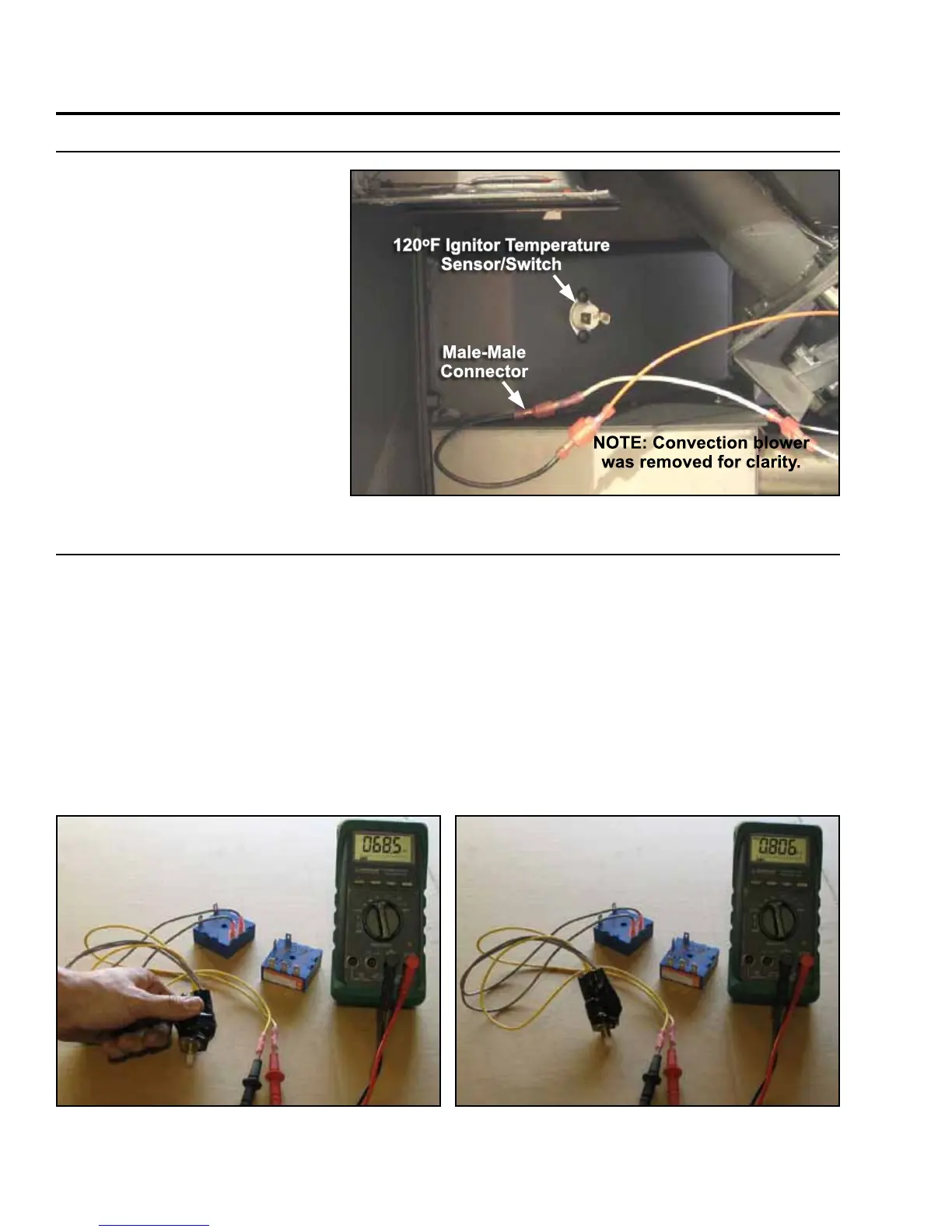
How To By-Pass THe 120°F igniTor TemPeraTure sensor/swiTCH:
Male-Male
Connector
NOTE: Convection blower
was removed for clarity.
120
o
F Ignitor Temperature
Sensor/Switch
Figure 34: By-Passing The 120
o
F Ignitor Temperature Sensor/Switch.
The 120°F ignitor temperature
sensor/switch is found on the air
channel behind the back panel.
Use a male-male connector to by-
pass the 120°F ignitor temperature
sensor/switch as shown in Figure
34.
Caution: Use care when removing
the wires, as the sensor can be
damaged.
Used in
trouBleShooting section “the
ignitor Will not Work”.
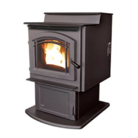
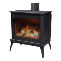
How To measure resisTanCe aCross THe dial-a-Fire:
This is for Timer Control models.
The dial-a-fire is found behind the right cabinet side.
Potentiometer Readings:
The potentiometer should have a range of approximately 68KΩ to 850 KΩ (± 10%).
Full counter-clockwise (switched off) = open circuit, overload or infinite resistance
Low fire 800 KΩ to 900 KΩ
High fire 68 KΩ to 82 KΩ (EF4 Timer Control 36.5 KΩ)
You should see a smooth increase/decrease, values shown in Figure 35 & 36 are: 68.5 – 806 KΩ.
Used in
trouBleShooting section “the auger timer Will not FunCtion normally - timer Control only“ & “the
auger timer Will not FunCtion normally - timer Control only“.
Figure 36: Measuring The Resistance Across The Dial-
A-Fire - High.
Figure 35: Measuring The Resistance Across The Dial-
A-Fire - Low.
38