EPSON LX-300+II/300+II RTP/1170II Revision D
LX-300+II RTP DISASSEMBLY AND ASSEMBLY 103
7.1.5 Main Board Assembly Removal
1. Remove the upper housing. (See 7.1.2 “Upper Housing Unit Removal”.)
2. Remove the printer mechanism. (See 7.1.3 “Printer Mechanism Removal”.)
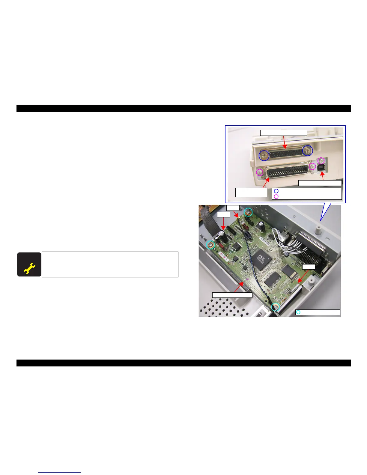
3. Remove 2 Jack Sockets (Torque 0.29-0.49 N.M.) securing the serial interface
connector to the lower shield plate.
4. Remove the serial interface connector from the installation hole of the lower shield
plate.
5. Remove 3 screws (C.P., Screw, 3x4 F/ZN; Torque 0.48-0.78 N.M.) securing the
parallel interface and USB interface to the lower shield plate.
6. Disconnect the panel FFC from CN12 on the board.
7. Disconnect the harness connected to the Cover Open Switch Assy from CN6 on
the board.
8. Disconnect the harness connected to the Power Supply Board Assembly from
CN8.
Press one edge of CN8 in order to remove or install the harness.
9. Remove 3 screws (C.B.P., Tite, 3x10 F/ZN) securing the main board assembly to
the lower housing.
Figure7-7. C640MAIN Board Assembly Removal
When the main board assembly is replaced, perform the destination
setting, Bi-D adjustment, top margin adjustment, and bottom margin
adjustment.

 Loading...


