EPSON LX-300+II/300+II RTP/1170II Revision D
Operating Principles Electrical Circuit Operating Principles 55
2.3.2 C294PSB / C294PSE Board
LX-300+II/1170II generates power supply by a power supply boards: either C294PSB
(100V) or C294PSE (200V) depending on local supplied voltage. The table below shows
the power supply boards input voltage specifications.
2.3.2.1 Electric Circuit
The power supply board supplies two types of power for control circuit and driving
mechanism. The table below shows output voltage and its use.
NOTE: *: Core voltage of CPU and G/A is 3.3V and it is generated by the
regulator IC on the MAIN board from +5VDC.
Table 2-15. Main Elements
Elements Location Function
CPU
(C640/641MAIN)
IC3
RISC C33208 CPU, QFP 128 pin
• Outside clock 48 MHz/
Inside clock 48 MHz
• 8KBRAM built-in
• Various DMA
• A/D converter
G/A
*
(C640/641MAIN)
IC6
Approximately 21000 gates, QFP 160 pin
• Bit manipulation
• Clock control
• interface control (IEEE1284/Type-B I/F)
• Input Buffer control
• Motor control
• Head control
CPU/GateArray
(C640/641MAIN)
IC3
CPU:
RISC C33208 CPU, QFP 128 pin
• Outside clock 19.66 MHz/
Inside clock 39.32 MHz
• 8KBRAM built-in
• Various DMA
• A/D converter
Approximately 21000 gates, QFP 160 pin
• Bit manipulation
• Clock control
• interface control (IEEE1284/Type-B I/F)
• Input Buffer control
• Motor control
• Head control
PROM IC7
4M / 8Mbit, DIP 40 / 42 pin
• Stores firmware
•CG
DRAM IC8
1/2/4M bit switching method, SPJ package 40 pin
• Various buffer, work area
EEPROM IC5
AT93C46, 1kbit, SOP 8pin
• Stores default value and various parameter
RESET IC IC4
M62030 (SANYO), 8 pin
• CPU and G/A reset
CR Motor Driver IC9 LB1847 (SANYO)
PF Motor Driver IC10 LB1847 (SANYO)
Serial I/F
Transceiver
IC2 HIN202CBN or equivalent
Regulator IC IC11
BA033 (ROHM) or equivalent
• Generates 3.3V logic voltage
Regulator IC IC12
PD494 or equivalent
• 95V rated voltage circuit
• Detects over voltage (over 150V) and sends OFF
signal to the power supply boards.
Thermistor TH1 Measures temperature of the motor driver.
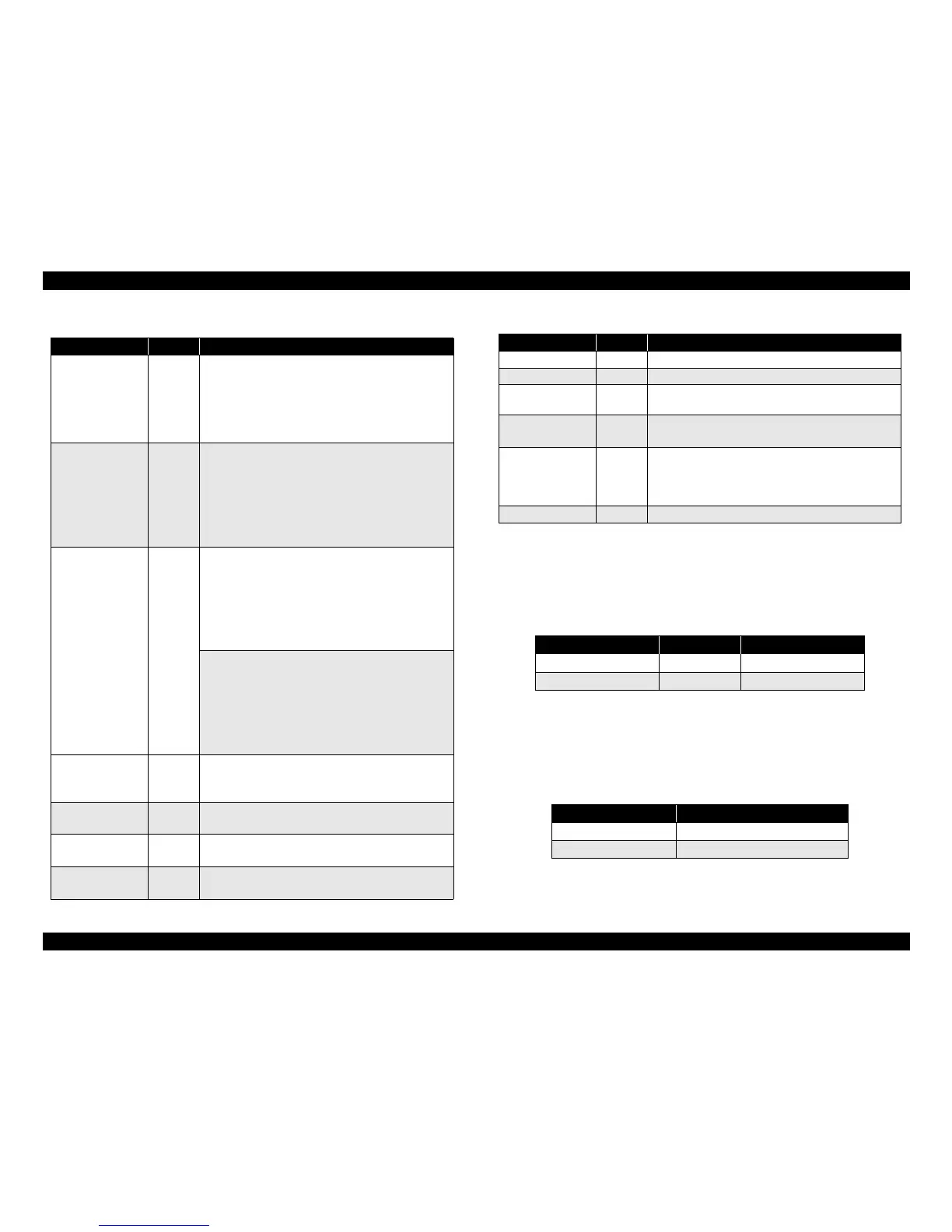
Table 2-16. Power Supply Boards Input Voltage Specifications
Circuit Input voltage Fuse specification
C294PSB 99 - 132VAC ULTSC-2.5A-NI
C294PSE 198 - 264VAC HT 1.25A
Table 2-17. Output Voltage and its Use
Output voltage Use
35 V +5%/ -10% Drive
5 V ± 5% Logic Voltage*
Table 2-15. Main Elements (continued)
Elements Location Function

 Loading...


