EPSON LX-300+II/300+II RTP/1170II Revision D
Disassembly and Assembly Disassembly and Assembly 75
4.2.6 P/S Board Assembly Removal
1. Remove the upper housing. (See 4.2.2 “Upper Housing Unit Removal”.)
2. Remove the printer mechanism. (See 4.2.3 “Printer Mechanism Removal”.)
3. LX-300+II: Remove 1 screw(C.B.P., Tite, 3x10 F/ZN;Torque 0.78-0.98 N.M.)
and the left grounding plate.
4. LX-1170II: Remove 1 screw (C.B(O), Screw, 4x8, F/ZN; Torque 0.98-1.18
N.M.) and the grounding cable.
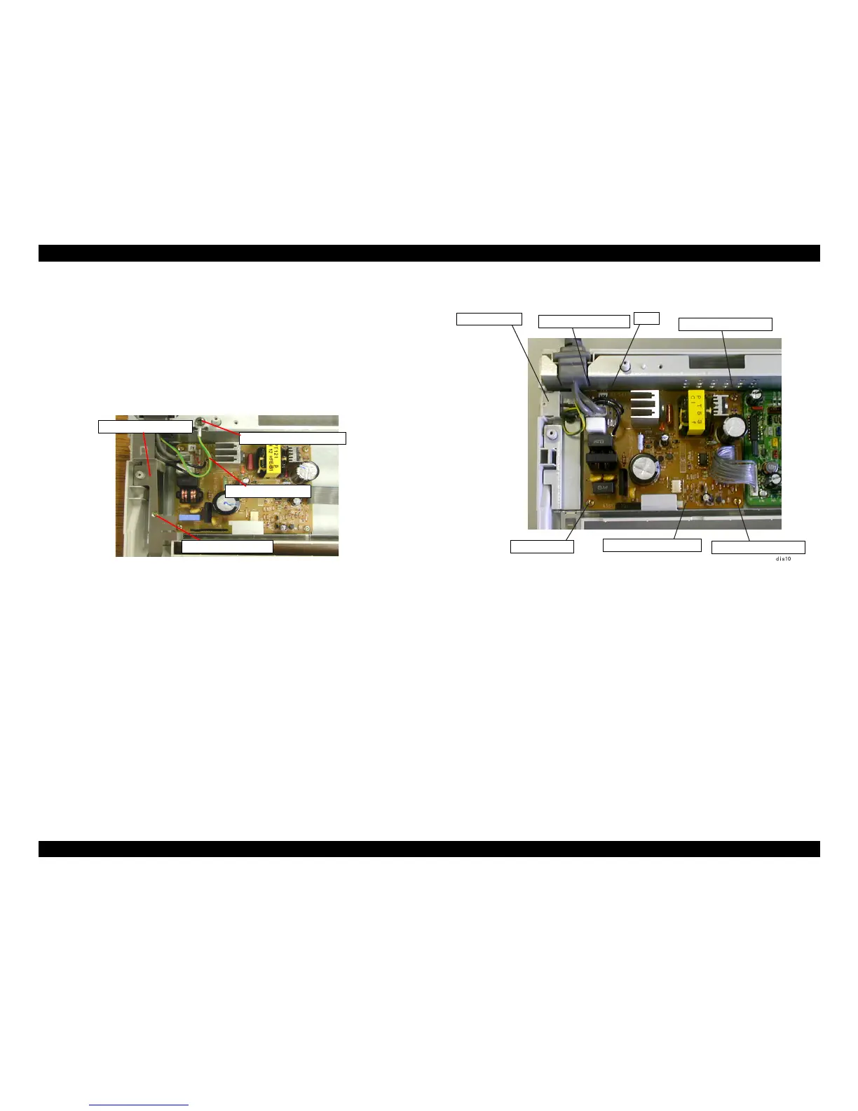
Figure 4-9. Ground Plate and Cable Removal (LX-1170II)
5. Remove the power cable (CN1) connecting to the Power Supply board assembly.
Remove the power switch from the lower housing.
6. Disconnect the harness connecting the Power Supply board assembly to the main board
assembly. (CN8 of the main board assembly)
Press one edge of CN8 in order to remove or install the harness.
7. Remove 4 screws (C.B.P., Tite, 3x10 F/ZN; Torque 0.78-0.98 N.M.) securing the
Power Supply board assembly to the lower housing.
8. Remove the Power Supply board assembly.
Figure4-10. Power Supply Board Assembly Removal

 Loading...


