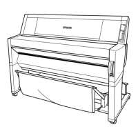
EPSON Stylus Pro 9500 Revision A
Operating Principles Component List & Illustrations 44
2.1 Component List & Illustrations
This section explains the print mechanism and operating principles for the
EPSON Stylus Pro 9500.
2.1.1 Print Mechanism Components
The printer mechanism of EPSON Stylus Pro 9500 consists of the following
mechanism parts.
Table 2-1. Print Mechanism Components
Component Explanation
Carriage Assembly Carriage section:
o printheads (B head/C head)
o PG Motor
o Linear Encoder
o HP sensor
o PG sensor
o Paper Width sensor
o Paper cutter-drive component
Carriage guide rail section:
o CR Motor
Paper Feed Mechanism Paper feed rail:
o Grid roller assembly
o Secondary roller assembly (opposite the grid rollers)
o PF Motor (Rotary Encoder internal part)
o Paper Suction Fans
o P_FRONT Sensor (detects front edge)
o P_REAR Sensor (detects rear edge)
o Paper Thickness Sensor
o Paper Release-Lever Position Sensor
Cleaning Assembly
o Pump Assembly/Pump Motor
o Cap Assembly
o CR Lock Mechanism
Ink Delivery System I/C Holder Assembly
o Ink Cartridge Holder/Valve Mechanism
o I/H Lever Position Sensor
o Ink Cartridge Detect Sensor
o Ink Low Sensor
o Ink ID Sensor
Other Cover Position Sensor (interlock switch)
Table 2-1. Print Mechanism Components
Component Explanation
 Loading...
