Confidential
EPSON
TITLE
SHEET
REVISION
NO
SHEETNEXT
20 19
TM-T81
Specification
(STANDARD)
A
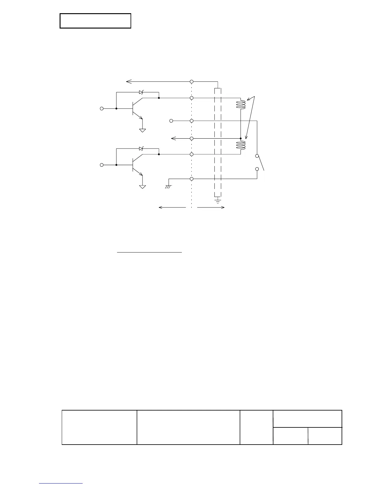
4) Drawer open/close signal
Input signal level (connector pin 3): "L" = 0 to 0.8 V
"H" = 2 to 5 V
Drawer kick-out connector
1
2
3
4
5
6
F. G
P-GND
P-GND
A
B
Printer side User side (Drawer kick-out side)
+24V
With shielded
Drawer kick-out solenoid
Drawer open/close switch
Figure 2.2.4 Drawer Circuitry
NOTES: 1. Use a shielded cable for the drawer connector cable.
2. Two driver transistors cannot be energized simultaneously.
3. The drawer drive duty must be as shown below.
ON time
(ON time + OFF time)
≤ 0.2
4. Be sure to use the printer power supply (connector pin 4) for the drawer power source.
5. The resistance of the drawer kick-out solenoid must not be less than the specified.
Otherwise, an overcurrent could damage the solenoid.
6. Do not connect telecommunication network to the drawer kick-out connector.
 Loading...