Confidential
EPSON
TITLE
SHEET
REVISION
NO
SHEETNEXT
19 18
TM-T81
Specification
(STANDARD)
A
2.2.3 Drawer Kick-out Connector (Modular Connector)
The pulse specified by ESC p or DLE DC4 is output to this connector. The host can confirm the
status of the input signal by using the DLE EOT, GS a, or GS r commands.
1) Pin assignments: See Table 2.2.2.
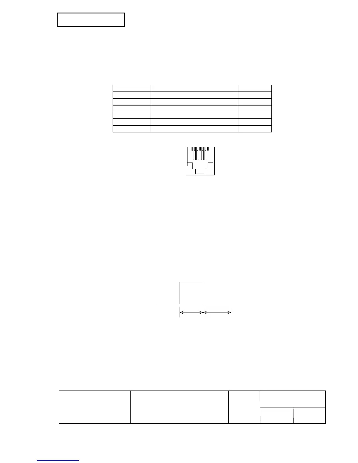
Table 2.2.2 Drawer Kick-out Connector Pin Assignments
Pin Number Signal Name Direction
1 Frame GND —
2 Drawer kick-out drive signal 1 Output
3 Drawer open/close signal Input
4 +24 V —
5 Drawer kick-out drive signal 2 Output
6 Signal GND —
+24 V is output through pin 4 when the power is turned on. However, pin 4 must be used only
for the drawer.
16
Figure 2.2.2 Drawer Kick-out Connector
2) Connector model: Printer side: MOLEX 52065-6615 or equivalent
User side: 6-position 6-contact (RJ12 telephone jack)
3) Drawer kick-out drive signal
Output signal: Output voltage: Approximately 24 V
Output current: 1 A or less
CAUTION: To avoid an overcurrent, the resistance of the drawer kick-out solenoid must be 24 Ω
or more.
Output waveform: Outputs the waveforms in Figure 2.2.3 to the points A and B in
Figure 2.2.4.
t1 (ON time) and t2 (OFF time) are specified by ESC p or DLE DC4.
t 1x 2 msec
t 1x 2 msec
Figure 2.2.3 Drawer Kick-out Drive Signal Output Waveform
t2 x 2 mst1 x 2 ms
 Loading...