VT6L Maintenance 12. Joint #4
VT series Maintenance Manual Rev.2 103
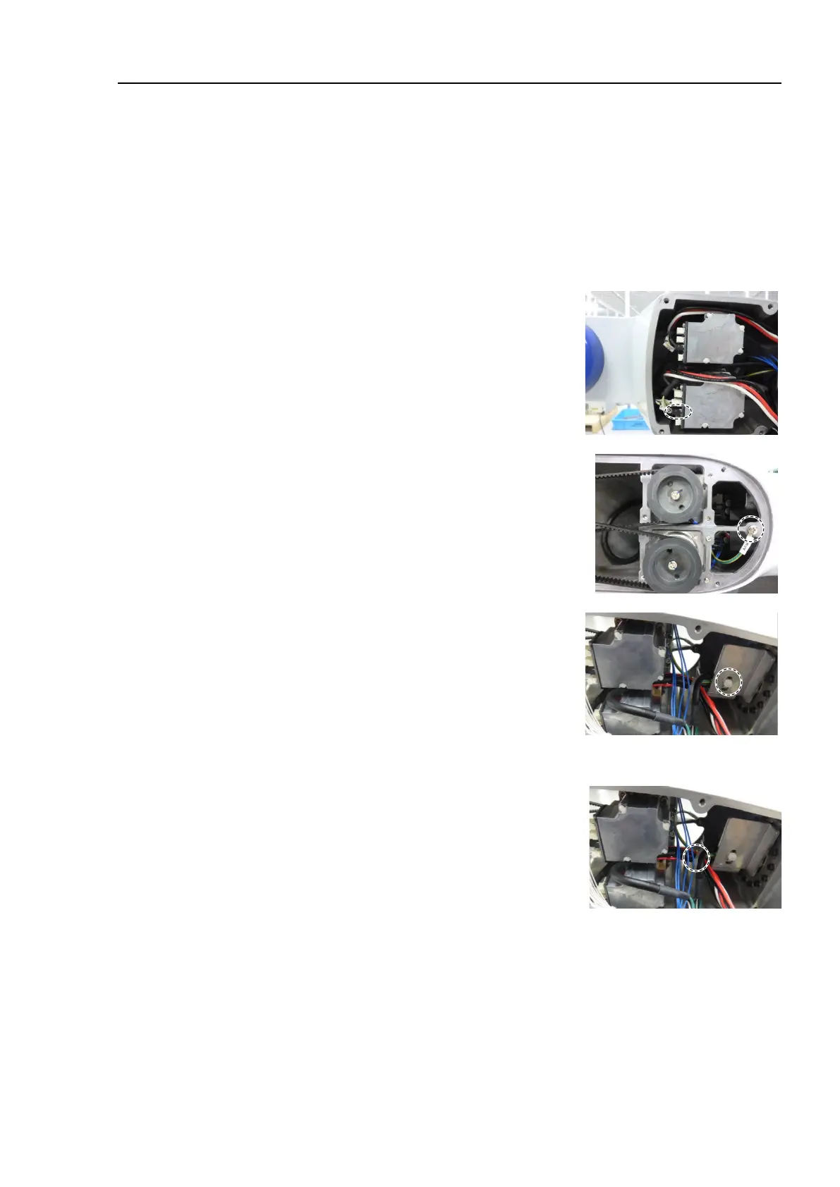
oint #4
the following cables through a new Joint #4 timing belt.
Power cable (Joint #5, 6 connector part)
Joint #5 signal cable (for motor)
Ground wire
the Joint #4 motor unit.
Reference: 12.1 Replacing Joint #4 Motor
Joint #4 Motor Installation step (1) through (8)
the Jo
int #5 signal cable connector (for
motor: black).
the ground wire terminals of the Arm #4.
Cross-recessed screw: M4×6
Tightening torque: 2.0 ± 0.1 N·m
Pass the wire tie through the hole on the plate
the Arm #4.
Bind the following cables with the wire tie.
Wire tie: AB150
Power cable
Signal cable (for motor)
Ground wire
the following cables with the wire tie.
Wire tie: AB100
Motor cable(Joint #5)
Signal cable (Joint #5)
Motor cable (Joint #6)
Ground wire
ount the following covers.
Arm #3 Cover
Arm #4 Cover 1
Arm #4 Cover 2
Reference: 7 Covers

 Loading...


