VT6L Maintenance 18. Controller Unit
140 VT series Maintenance Manual Rev.2
rotection
1)
ount the base rear gasket in the groove on the back of the base.
2)
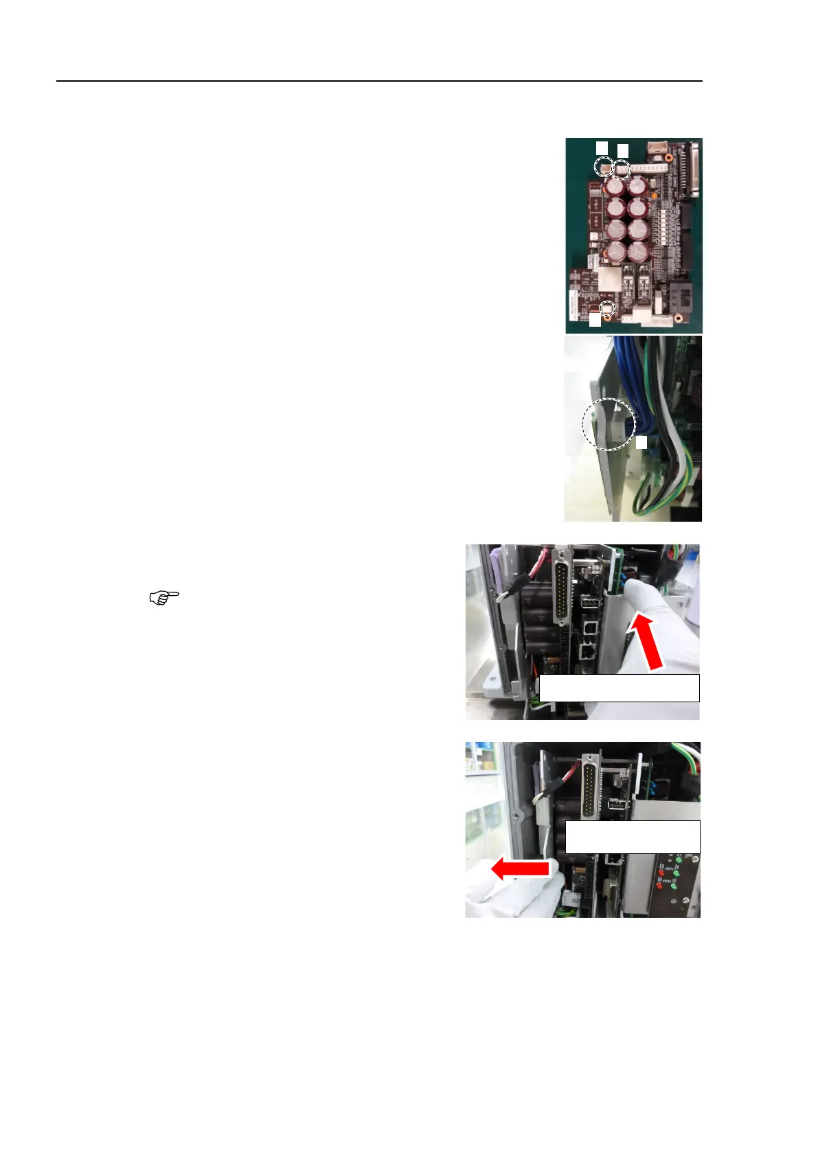
the following connectors to
Controller Unit.
A: Power cable connector
B: Signal cable connector
C: LED connectors × 2
G: TP connector
3)
the Controller Unit into the base.
Insert the Controller Unit while moving it
to the right (see the
picture).
Then, gently move the plate of the
Controller Unit to
the left and let the
thermal conductive sheet contacts with the
wall inside
the base.
Move it to the right to insert

 Loading...


