38
5.
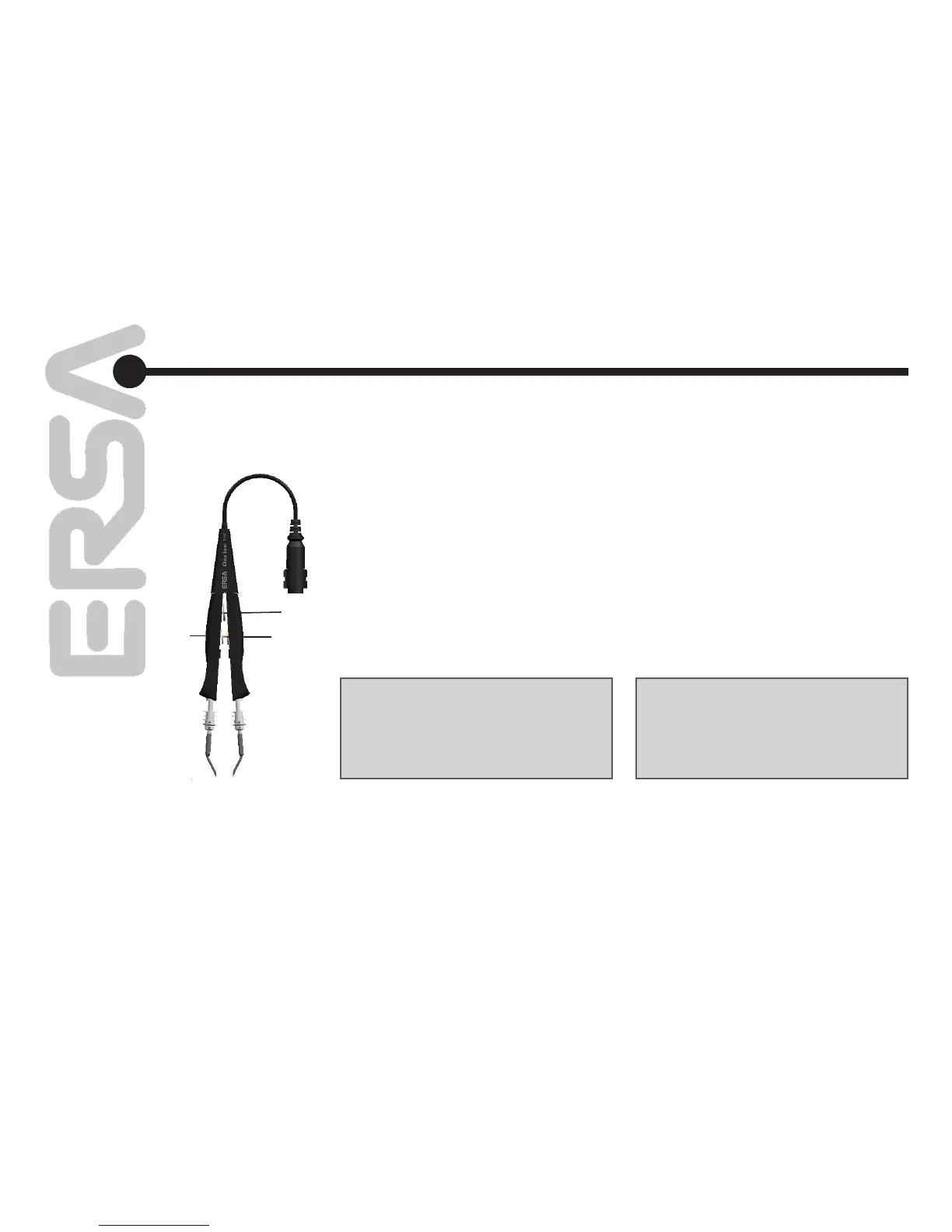
Ограничительные механизмы
Термопинцет Chip tool имеет
ограничительный винт для предотвращения
от чрезмерного сжатия компонентов (поз. 1
на рис. 13). При его настройке убедитесь в
том, что сегменты термопинцета сомкнуты,
а рабочие грани насадок едва касаются друг
друга.
Затем зажмите винт 2. Максимальный угол
разведения сегментов термопинцета можно
ограничить винтом 3. Это особенно удобно
при демонтаже компонентов из печатных
плат с плотным монтажом.
3
2
1
Adapting to the component size
The limit position for the force-limitation device in
the Chip tool is adjusted using the knurled head
screw 1 (Fig. 13). When making this adjustment,
be sure that when the tool is closed, the des
-
oldering inserts only touch one another and do
not bend.
Then fasten knurled nut 2. This counters knurled
head screw 1 and thus prevents self-adjustment
of the force-limitation device.
The opening angle of the Chip tool may be
adjusted using knurled head screw 3.
This function is extremely useful for working with
densely-populated printed circuit boards.
Примечание:
Если термопинцет Chip tool долгое время
не используется, оставляйте сегменты в
максимально разведенном положении,
чтобы пружина дольше сохраняла свои
свойства.
Note:
When not using the Chip tool for a long period
of time, please open the angle to its widest
position using the knurled head screw 3. Fail-
ure to do so will result in a slight weakening of
the spring mechanism.
рис. 13 / fig. 13
Функциональное
описание
Functional description