46
6.
6.3 Другие ситуации
Станция постоянно отображает комнатную
температуру.
• Неисправность соединительного кабеля
или нагревательного элемента TechTool
или PowerTool.
• Станция показывает необычно высокую
температуру.
• Вероятная причина в неисправности
нагревательного элемента термопинцета
ChipTool.
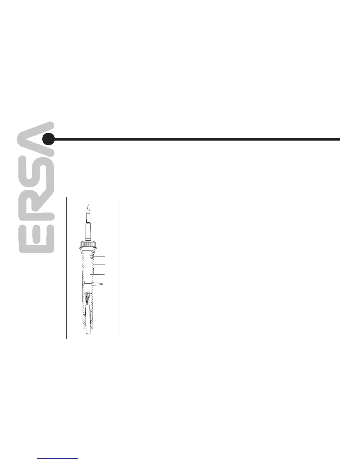
6.4 Замена нагревательного
элемента
Перед заменой нагревательного элемента
отключите инструмент от управляющего
блока станции и дайте ему остыть.
TechTool
(рис. 19)
• Выверните крепежный винт ручки (поз. 1).
• Снимите ручку (поз. 2).
• Отсоедините (поз. 4) нагревательный
элемент от кабеля.
• Замените нагревательный элемент (поз. 3).
• Соедините (поз. 4) нагревательный
элемент с кабелем.
• Наденьте ручку (поз. 2) на нагревательный
элемент (поз. 3).
• Заверните крепежный винт ручки (поз. 1)
6.3 Other Errors
Other errors may also occur, indicating possible
defects in the soldering tool.
These errors are:
• The station permanently displays only the room
temperature. In this case, there is a defect in
the heating element or cable with thermocou
-
ple-controlled soldering irons (Power tool,
Tech tool).
• The station permanently displays an actual
temperature that is too high. This error can
occur during operation of Chip tool. In this
case, switch off the station and replace the tool
with an intact one.
6.4 Changing the Heating Element
Before changing a heating element, switch off
the device at the mains switch and pull the con
-
necting plug of the soldering tool.
Allow the device to cool for a few minutes.
Tech tool
• Unscrew handle mounting screw (pos. 1 /
fig. 19).
• Pull off handle (pos. 2 / fig. 19).
• Disconnect plug connection (pos. 4 / fig. 19)
between heating element and cable.
• Replace heating head (pos. 3 / fig. 19).
• Restore plug connection (pos. 4 / fig. 19)
between heating element and cable.
• Push handle (pos. 2 / fig. 19) onto heating
head (pos.3 / fig. 19).
•
Screw in handle mounting screw (pos. 1 / fig. 19).
1
2
3
4
5
рис. 19 / Fig. 19
Диагностика
неисправностей
Error Diagnosis
and Troubleshooting