42
• Determine the temperature of the soldering
tip using a calibrated gauge (e.g. ERSA DTM
100).
• Compare the two display values.
• Compute the temperature difference, with
∆T = T
DIGITAL 2000A
– T
gauge
• Set the computed temperature difference ∆T
(with sign) in the menu item „Calibration” by
means of the (+) and (-) keys.
Примечание:
погрешности могут быть обусловлены
также движением воздуха.
Note:
To avoid measurement errors, ensure calm air
conditions.
5.
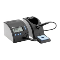
5.9 Текущая температура (°C / °F)
Когда устройство не находится в режиме
настройки параметров, на дисплее
отображается текущая температура,
измеряемая термосенсором. Мерцающая
точка над первой цифрой (левым
знакоместом дисплея – рис. 15) означает
циклы нагрева: при ее свечении
нагревательный элемент активен. Четвертое
(крайнее правое) знакоместо отображает
символ шкалы – Цельсия (С) или Фаренгейта
(F). Во втором случае при превышении 999
четвертое знакоместо используется для
отображения дополнительной цифры.
5.9 Actual temperature (°C / °F)
Provided that no operating mode has been
chosen the actual temperature of the soldering
tip or temperature sensor is displayed on the sol
-
dering station.
The first digit‘s decimal point (fig. 15) indicates
the operating status of the heating element. As
long as this point shines, the heating element
is triggered. The fourth digit of the LED display
indicates the selected temperature unit (°C / °F).
If °F has been selected, and the actual tempera
-
ture rises above 999, the fourth digit of the LED
is used to fully display the temperature.
325
C
рис. 15 / fig. 15
в режиме калибровки, пользуясь кнопками
“+” и “–”.
Для снижения погрешностей измерения
жало паяльника должно быть чистым, а
температура воздуха неизменной.
Функциональное
описание
Functional description