48
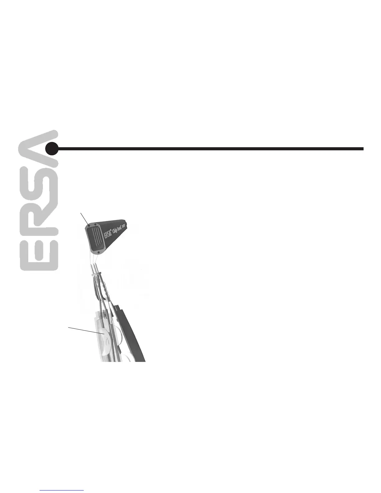
Замена нагревательных элементов в
термопинцете ChipTool
На отключенном инструменте осторожно
стяните кожух в направлении стрелки (1).
Выньте насадки для выпаивания (2) согласно
параграфу 5.3. Отвинтите ключом 3N472
элементы (3) против часовой стрелки и
снимите в направлении (4). Сместите
рукоятки примерно на 2 см в направлении
(5). Освободите зацеп (6) и снимите рукоятки
в направлении (7). Выньте нагревательный
элемент из разъема (8) и удалите по
диагонали в направлении (9).
• Произведите замену нагревателей
обязательно парами (артикул 42200J).
• Cоберите изделие в порядке,
противоположном разборке, обращая
внимание
• на положение пружины - короткой
стороной к разъему (рис. 20, 21).
• На кожухе (рис. 20, 21) имеются
обозначения для корректного соединения
в разъем.
6.
Chipp tool -
Changing the heating element
Switch off the soldering station and carefully pull
off the connecting sleeve in the direction of the
arrow (1).
Pull off the de-soldering insert as described
under point 5.3 (2).
Unscrew the tip receptacle with the slot key
(3N472) counterclockwise (3) and remove in the
direction of the arrow.
Push the handle approximately 2 cm in the direc
-
tion of the arrow (5).
Lift the hook out of the bearing plate from behind
(6) and remove in the direction of the arrow (7).
Pull the heating element out of the plug contact
(8) and remove diagonally in the direction of the
arrow (9).
• Only replace heating elements (042100J) in
pairs.
• Assemble in the reverse sequence.
• Note the install position of the leaf springs
– the short side is in the direction of the plug
connection.
• The points on the lower side of the connection
sleeve indicate the pin arrangement for plug
-
ging in.
схема соединений
изображена на кожухе
Illustration pin arrangement
положение пружины
Leaf spring install position
рис. 21 / Fig. 21
Диагностика
неисправностей
Error Diagnosis
and Troubleshooting