CUTMASTER A120
0-5430 INTRODUCTION
2T-1
SECTION 2 TORCH:
INTRODUCTION
2T.01 Scope of Manual
This manual contains descriptions, operating instructions
and maintenance procedures for the 1Torch Models
SL100/Manual and SL100/Mechanized Plasma Cutting
Torches. Service of this equipment is restricted to prop-
erly trained personnel; unqualied personnel are strictly
cautioned against attempting repairs or adjustments not
covered in this manual, at the risk of voiding the Warranty.
Read this manual thoroughly. A complete understanding
of the characteristics and capabilities of this equipment
will assure the dependable operation for which it was
designed.
2T.02 General Description
Plasma torches are similar in design to the automotive
spark plug. They consist of negative and positive sec-
tions separated by a center insulator. Inside the torch,
the pilot arc starts in the gap between the negatively
charged electrode and the positively charged tip. Once
the pilot arc has ionized the plasma gas, the superheated
column of gas ows through the small orice in the torch
tip, which is focused on the metal to be cut.
A single torch lead provides gas from a single source to
be used as both the plasma and secondary gas. The
air ow is divided inside the torch head. Single - gas
operation provides a smaller sized torch and inexpensive
operation.
NOTE!
Refer to Section "2T.05 Introduction
to Plasma" on page 2T-2, for a more
detailed description of plasma torch
operation.
Refer to the Appendix Pages for ad-
ditional specications as related to the
Power Supply used.
2T.03 Specications
A. TorchCongurations
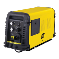
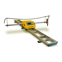
1. Automation Torch, Model
The standard automation torch has a position-
ing tube with rack & pinch block assembly and a
solenoid valve.
Art # A-07402_AC
1.75" /
1.375" / 35 mm
0.625" /
4.95" / 126 mm
12.285" / 312 mm
/
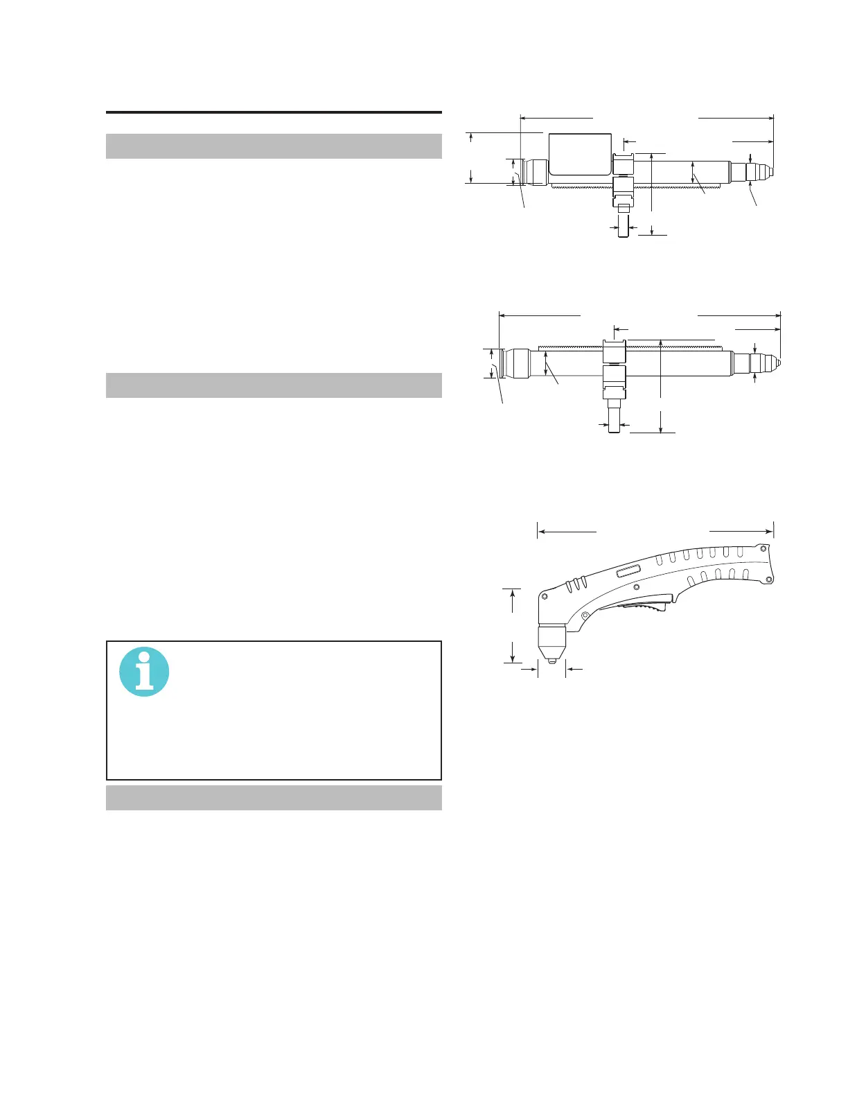
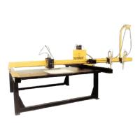
2. Machine Torch, Model
The standard machine torch has a positioning
tube with rack & pinch block assembly.
Ar
1.75" /
44.5 mm
1.375" / 35 mm
0.625" /
4.95" / 126 mm
1.175" / 30 mm
9.285" / 236 mm
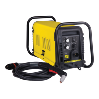
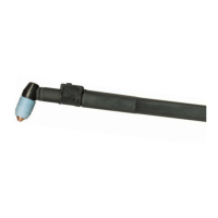
3. Hand/Manual Torch, Models
The hand torch head is at 75° to the torch handle.
The hand torches include a torch handle and torch
trigger assembly.
10.125" (257 mm)
3.75"
1.17" (29 mm)
Art # A-03322_AB
B. Torch Leads Lengths
Hand Torches are available as follows:
• 20 ft / 6.1 m, with ATC connectors
• 50 ft / 15.2 m, with ATC connectors
Machine / Automation Torches are available as
follows:
• 5 foot / 1.5 m, with ATC connectors
• 10 foot / 3.05 m, with ATC connectors
• 25 foot / 7.6 m, with ATC connectors
• 50 foot / 15.2 m, with ATC connectors
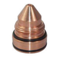
C. Torch Parts
Starter Cartridge, Electrode, Tip, Shield Cup
D. Parts - In - Place (PIP)
Torch Head has built - in switch