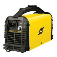
CUTMASTER A120
INSTALLATION 0-5430
3-2
Most units are shipped from the factory with a 230 Volt
input power cable wired to the input contactor in the
single - phase conguration. The following illustrations
and directions are for changing that conguration to a
different voltage and or to three - phase operation or back
again if a change had already been made.
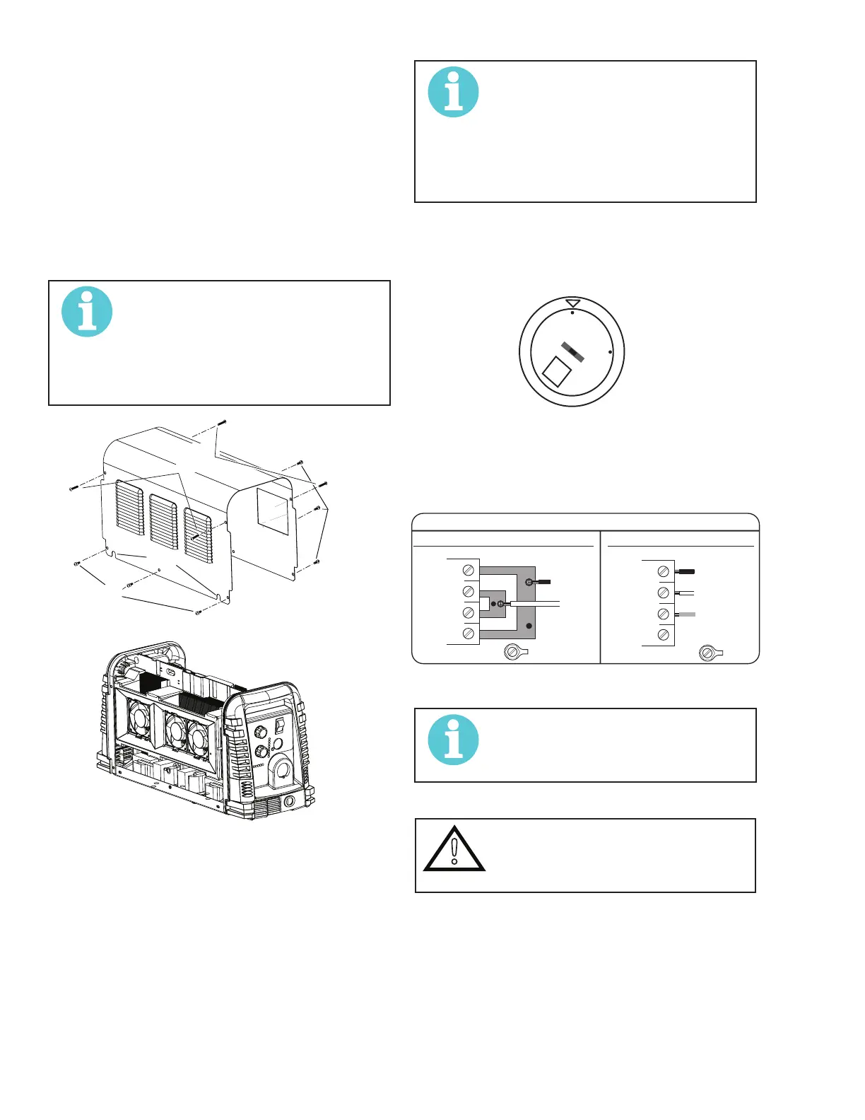
A. Cover Removal
1. Remove the upper and lower screws which
secure the cover to the main assembly. Do not
loosen the lower screws inside the cut out slots
in the bottom of the cover.
NOTE!
The upper screws and lower screws
are not the same. Do not mix them.
The upper screws are for threading into
the plastic of the front and rear panels.
DO NOT use the ner threaded lower
screws for this.
Art # A-08429
Lower
Screws
Lower
Slots
Upper
Screws
2. Carefully pull the Cover up and away from the
unit.
B. Cover Installation
1. Reverse previous procedures for cover installa-
tion.
NOTE!
When installing the upper screws, at-
tempt to reuse the original threads. The
easiest way to do this is by turning the
screw counter-clockwise until you feel
the threads line up, then begin to turn
the screw clockwise to tighten. Do not
over tighten.
C. Input Power Selection
Set the Input Voltage Selection Switch at the rear of the
unit based on the primary input voltage it is connected
to. Low is 208/230 VAC and high is 460 VAC.
S
LO
HI
D. Quick Guide to Phase Wiring
The following illustration and directions are for changing
phase of the power supply.
Input Power Cable Connections
Three-Phase (3ø)
Store copper jumpers on base plate
Single-Phase (1ø) and Jumper Settings
GND
L1
L2
L3
L4
GND
L1
L2
L3
L4
Single and Three Phase Input Power Wiring
NOTE!
There are two jumpers used for the
single phase 230V setting and none for
three phase.
E. Connections to Single Phase Input Power
!
WARNING
Disconnect input power from the power
supply and input cable before attempt-
ing this procedure.
These instructions are for changing the input power and
or cable on the 208/230, 400, 460 VAC Power Supply to
Single - Phase input power.