CUTMASTER A120
OPERATION 0-5430
4-2
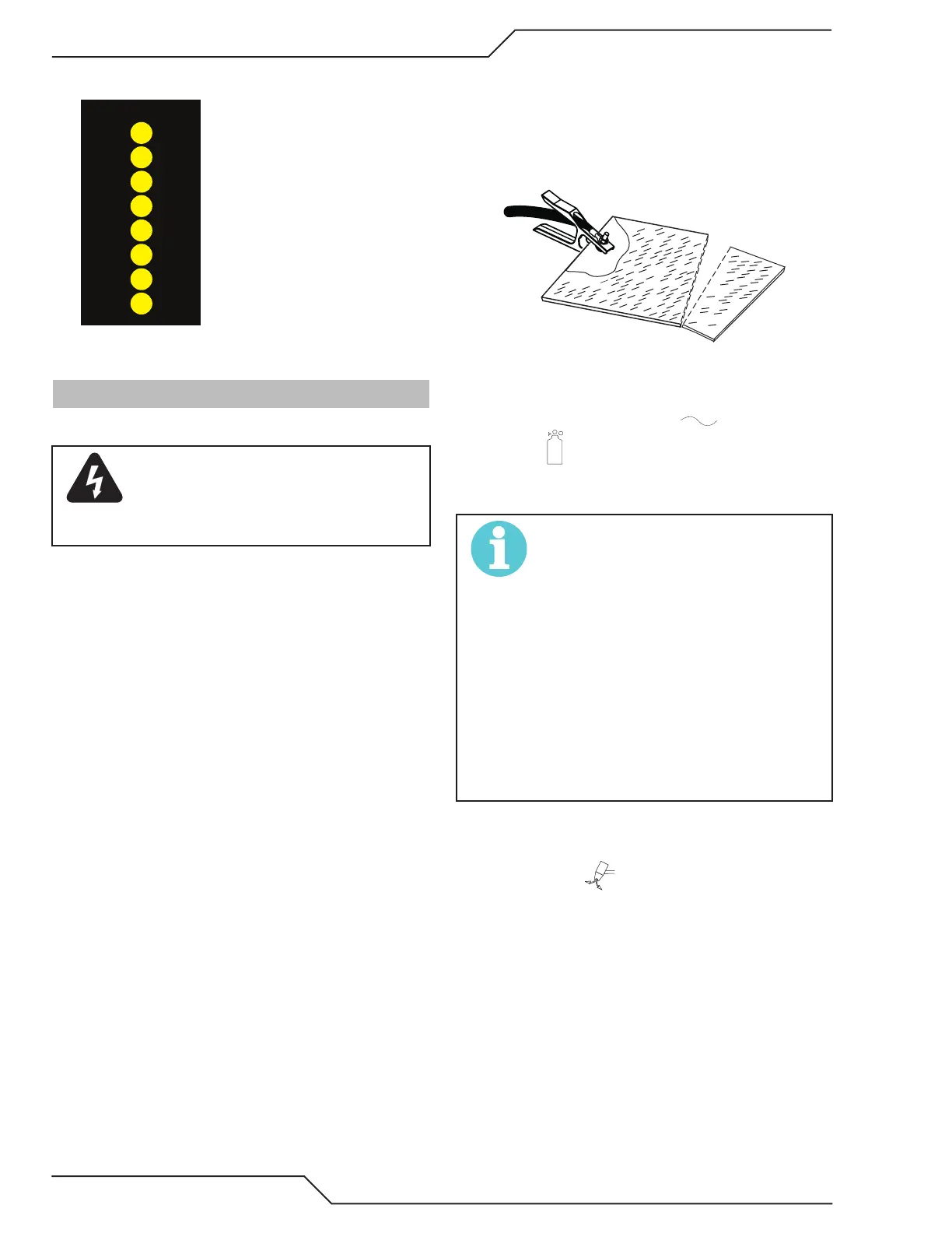
10. Pressure Indicators
PSI BAR
MAX MAX
MINMIN
80
75
70
65
5.5
85 5.9
90 6.3
5.2
4.8
4.5
The Indicators will illuminate according to the pres-
sure set by the Pressure Control Knob (number 4).
4.02 Preparations for Operation
At the start of each operating session:
WARNING
Disconnect primary power at the source
before assembling or disassembling
power supply, torch parts, or torch and
leads assemblies.
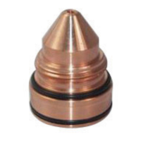
Torch Parts Selection
Check the torch for proper assembly and appropriate
torch parts. The torch parts must correspond with
the type of operation, and with the amperage output
of this Power Supply (120 amps maximum). Refer to
Section 4T.07 and following for torch parts selection.
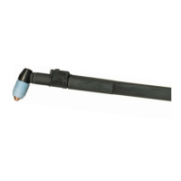
Torch Connection
Check that the torch is properly connected. Only
ESAB model SL100 / Manual or SL100 / Mechani-
cal Torches may be connected to this Power Supply.
See Section 3T of this manual.
Check Primary Input Power Source
1. Check the power source for proper input volt-
age. Make sure the input power source meets
the power requirements for the unit per Section
2, Specications.
2. Connect the input power cable (or close the main
disconnect switch) to supply power to the system.
Air Source
Ensure source meets requirements (refer to Section
2). Check connections and turn air supply ON.
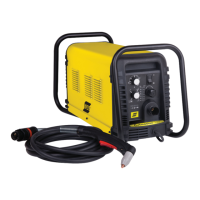
Connect Work Cable
Clamp the work cable to the workpiece or cutting
table. The area must be free from oil, paint and rust.
Connect only to the main part of the workpiece; do
not connect to the part to be cut off.
Power ON
Place the Power Supply ON / OFF switch to the ON
(up) position. AC indicator turns ON. Gas
indicator turns ON if there is sufcient gas pres-
sure for power supply operation and the cooling
fans turn ON.
NOTE!
Minimum pressure for power supply op-
eration is lower than minimum for torch
operation.
The cooling fans will turn ON as soon
as the unit is turned ON. After the unit
is idle for ten (10) minutes the fans will
turn OFF. The fans will come back ON
as soon as the torch switch (Start Sig-
nal) is activated or if the unit is turned
OFF, then turned ON again. If an over
temperature condition occurs, the fans
will continue to run while the condition
exists and for a ten (10) minute period
once the condition is cleared.
Set Operating Pressure
1. Place the Power Supply Function Control knob
to the SET position. Gas will ow.
2. For Standoff cutting, adjust gas pressure from 70
- 85 psi / 4.8 - 5.9 bar (LED's in center of control
panel). Refer to the Standoff chart for pressure
setting details.