CUTMASTER A120
INSTALLATION 0-5430
3T-2
3T.03 Automation Interface PCB with Ohmic Sense
The new Automation Interface PCB with Ohmic Sense adds additional selectable divided voltage ratios and
selectable polarity of the divided signal. The board also has Ohmic sensing for use with the iHC XT via
either the exposed torch tip or via a separate Shield Cup using the Ohmic clip. The ohmic sensing will also
provide collision sensing when used with the iHC XT or iCNC.
Signals at the CNC connector (J1 on this board) are START / STOP on J1-3 (common) and J1-4 (+); Isolated
& Divided Arc voltage on J1-5 (-) and J1-6 (+); PLATE CONTACT OUT (relay contact) between J1-10 and
J1-11; OK TO MOVE OUT (relay contact) between J1-12 and J1-14.
Voltage divider;
The 6 position DIP switch, DIV1, makes available the following divide ratios:
DIV1-1 ON = 16.7:1 for SC11; DIV1-2 ON = 20:1 for EASB; DIV1-3 ON = 30:1;
DIV1-4 ON = 40:1 for Inova; DIV1-5 ON = 50:1 for IHT, SC3000 & 3100; Hypertherm
®
;
DIV1-6 ON = 80:1 for TD iHC
NOTE!
Only one position should be on at a time.
Divided arc voltage signal is isolated, either the positive signal (J1-6) or negative (J1-5) may be grounded
or both can be oating.
Ohmic sensing and Collision via exposed TIP:
With a connection made from the PCB4 terminal TIP to the main board PCB1 terminal TIP1 contact of the
exposed tip with the work while nding height is sensed and activates the signal PLATE CONTACT OUT at
J1-11. SW2 set to 0 can disable this sensing.
During cutting the exposed tip contacting the work will close the relay contact between J1-10 and J1-11
which is interpreted by the iHC as a collision. This feature may be disabled by setting SW3 to 0.
NOTE!
If TIP1 on PCB1 (main board) is not connected to TIP terminal on PCB4 both SW2 and SW3 must
be set to “0” (off) position else the plate contact signal will be active all the time.
Ohmic sensing and Collision via shield cup Ohmic Clip.
The Plasma Adapter Cable for use with the iHC XT for this Automation Interface PCB with Ohmic Sense
includes a connection to pin 13 which can be connected to a wire from the ohmic clip. Note that this adapter
cable is different from the one used with the separate iHC voltage divider board. When the shield cup, with
contact from the ohmic clip, contacts work during height nding it closes the relay between J1-10 and J1-11
providing the PLATE CONTACT signal to the iHC. During cutting the iHC interprets this contact as a collision
and retracts the torch.
Indicators:
LED indicators START, M-ARC and CONTACT are provided to show when START (torch trigger) is ON,
when OK to Move (M-ARC) is on, and when Plate Contact is active.
Rating:
The OK to Move and the Plate Contact Out are relay contacts rated for maximum of 30VAC or DC at 1 amp
maximum.
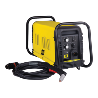
Start SW input requires a switch or relay contact rated for at least 12VDC at 3 ma.
J1-3
START
3k
J1-4