CUTMASTER A120
0-5430 OPERATION
4-1
SECTION 4 SYSTEM:
OPERATION
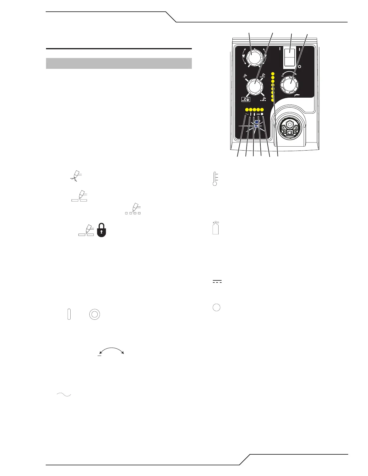
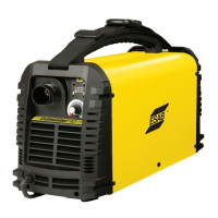
4.01 Front Panel Controls / Features
See Illustration for numbering Identification
1. Output Current Control
Sets the desired output current. Output settings
up to 60 Amps may be used for drag cutting (with
the torch tip contacting the workpiece) or higher for
standoff cutting.
2. Function Control
Function Control Knob, Used to select between the
different operating modes.
SET Used to purge the air through the unit
and torch and leads and to adjust gas pressure.
RUN Used for general cutting operations
RAPID AUTO RESTART Allows for faster
restarting of the Pilot Arc for uninterrupted cutting.
LATCH Used for longer hand held or
mechanical cuts. (Does not apply to automation).
Once a cutting arc is established, the torch switch
can be released. The cutting arc will remain ON
until the torch is lifted away from the work piece,
the torch leaves the edge of the work piece the
torch switch is activated again or if one of the sys-
tem interlocks is activated.
3. ON OFF Power Switch
ON / OFF Switch controls input power to the
power supply. Up is ON, down is OFF.
4. Air/Gas Pressure Control
The Pressure
Control is used in the
"SET" mode to adjust the air/gas pressure. Pull the
knob out to adjust and push in to lock.
5. AC Indicator
Steady light indicates power supply is ready for op-
eration. Blinking light indicates unit is in protective
interlock mode. Shut unit OFF, shut OFF or discon-
nect input power, correct the fault, and restart the
unit. Refer to Section 5 for details.
A
+
PSI BAR
MAXMAX
MINMIN
!
4
8
Art# A-07886
MIN
MAX
6. Temp Indicator
Indicator is normally OFF. Indicator is ON when
internal temperature exceeds normal limits. Let the
unit cool before continuing operation.
7. Gas Indicator
Indicator is ON when minimum input gas pressure
for power supply operation is present. Minimum
pressure for power supply operation is not sufcient
for torch operation.
8. DC Indicator
Indicator is ON when DC output circuit is active.
9.
Fault Error Indicator
Indicator is ON when Fault circuit is active. See sec-
tion 5 for explanations of fault lights.