◦ Lens curve tracking: the camber of the groove is adjustable.
3. Lens thickness
◦ Maximum lens thickness - represented by the white square along the shape
◦ Minimum lens thickness - represented by the red square along the shape
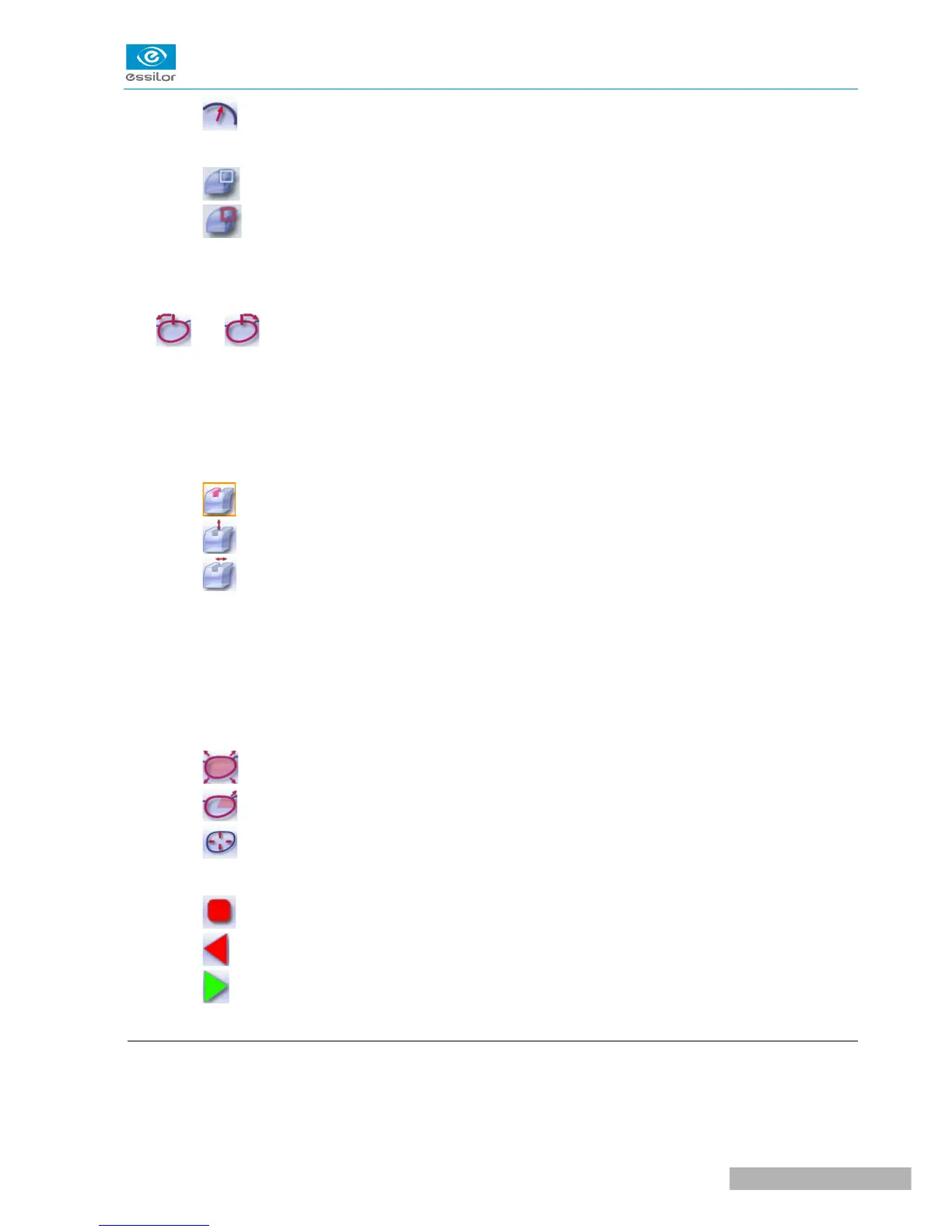
4. Cursor movement
The cursor is represented by the green square along the shape. To move it, select it directly or use the
and buttons.
5. Zoom window
Distance between the edges of the groove and the front & rear surfaces of the lens at the position of the
cursor.
6. Groove settings
◦ Distribution value - according to the type of customized groove selected
◦ Groove depth (in mm)
◦ Groove width (in mm)
7. Modify the selected setting
8. Groove trajectory
Flat representation of the lens making it possible to measure the distances between the groove and the
front & rear surfaces of the lens.
9. Modify the trajectory
◦ General modification of the groove curve
◦ Modification of a point in the groove curve
◦ Displacement of the groove curve
10. Navigation
◦ Stop the cycle
◦ Back to the main edging screen
◦ Start the edging cycle
c. Customized grooving
The use of the customized groove depends on 2 parameters: the frame and the lens. Before starting your
job, identify the major constraint.