ES4455.2 Load Carrier Board - User’s Guide 33
ETAS Properties and Functions
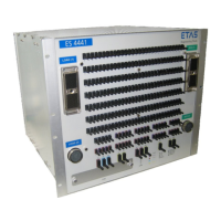
3. Place the ES4450.3, ES4451.4, ES4452.1,
ES4453.1,ES4457.1 or the ES4458.1 on its load
side (see Fig. 2-12 on page 33).
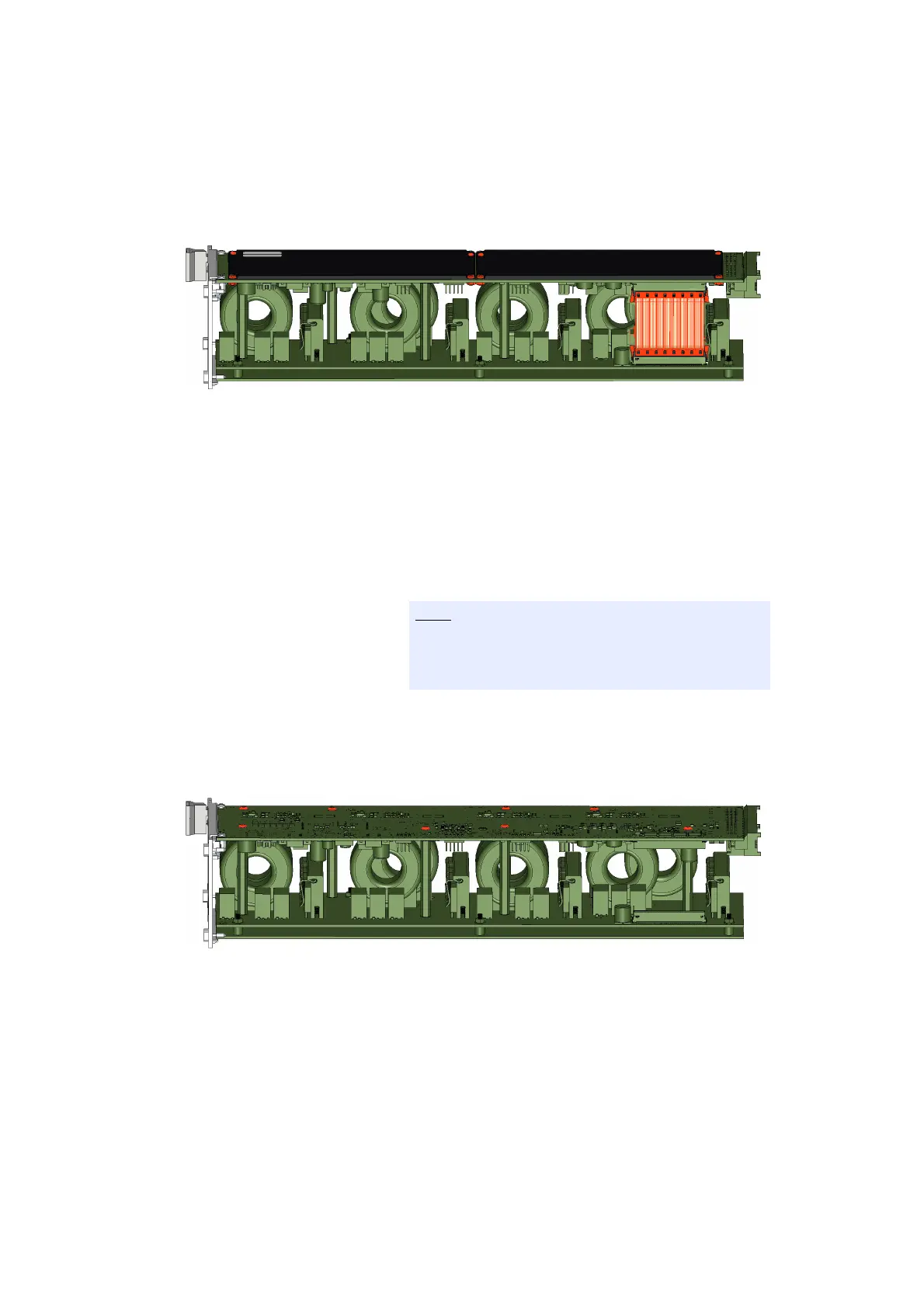
Fig. 2-12 Position of the ES4455.2 Load Carrier Board (top) with load module
(bottom).
4. For the variants ES4452.1, ES4453.1,ES4457.1 and
ES4458.1: Loosen the ribbon cable between the
ES4455.2 Load Carrier Board and the load module.
5. Loosen the screws of the plastic cover with a PZ0
screwdriver while holding the screw nut under-
neath it with a hexagon drive of size 5 (see Fig. 2-12
on page 33).
6. Remove the plastic covers.
7. Loosen the screws on the ES4455.2 Load Carrier
Board with a T8 screwdriver (see Fig. 2-13
on page 33).
Fig. 2-13 ES4455.2 Load Carrier Board with load module after removing the
plastic covers. The screws are marked in red.
The screws are made of plastic. Carefully loosen the
screws and carefully tighten them again during
installation to avoid damaging them.