ES4455.2 Load Carrier Board - User’s Guide34
Properties and Functions ETAS
8. Carefully lift the ES4455.2 Load Carrier Board and
remove it.
9. Remove the defective fuses from the ES4455.2
Load Carrier Board with small pliers (ca. 2 mm wide)
(see Fig. 2-11).
10.Install the new fuse according to Tab. 2-1
on page 31 and Fig. 2-11 on page 31.
11.Reinstall the ES4455.2 Load Carrier Board on the
load module in reverse order. Observe the "Proce-
dure for Installation and Removal" on page 28 for
this purpose.
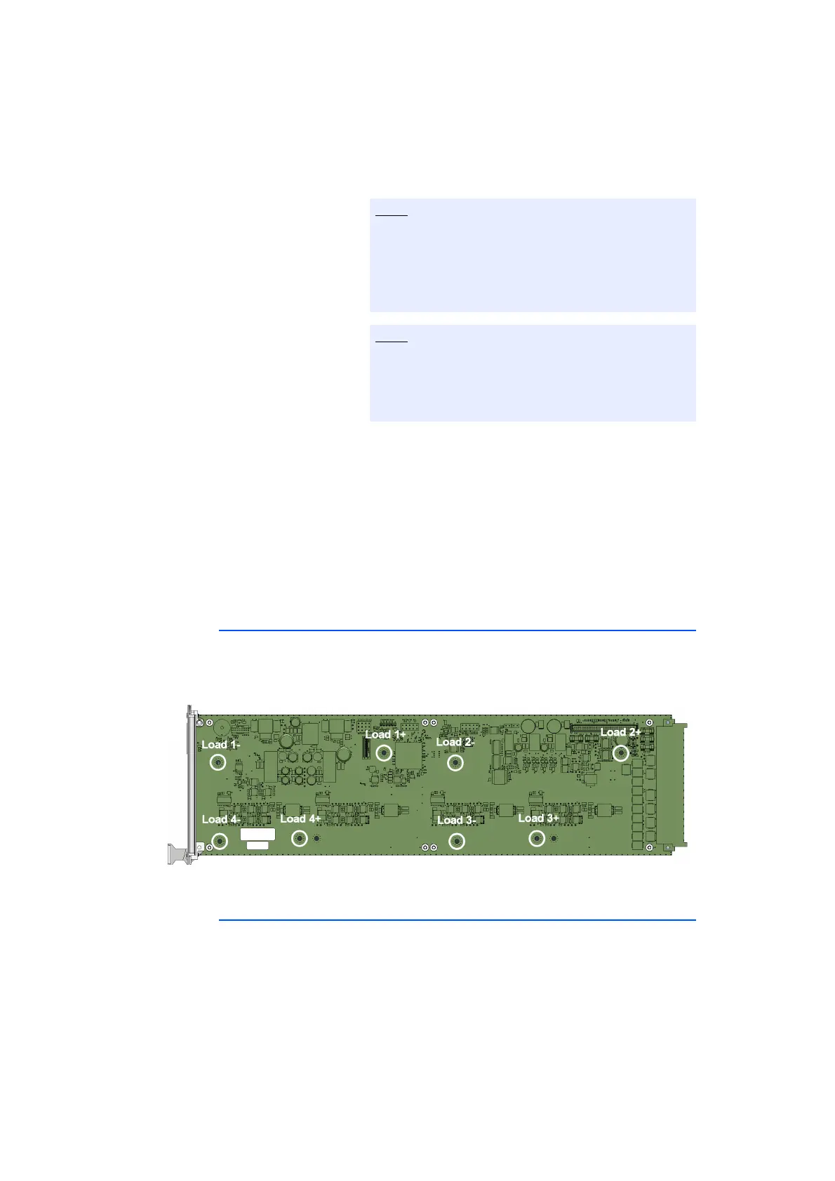
2.5 Interface for Load Modules on the ES4455.2 Load Carrier Board
The loads on the ES4455.2 Load Carrier Board are contacted via the spacer bolts.
Access to the loads is implemented via the backplane connector CO200
(page 37) by the spacer bolts. Fig. 2-14 on page 34 shows the signal assignment
of the contacts of the spacer bolts on the ES4455.2 Load Carrier Board.
Fig. 2-14 ES4455.2 Load Carrier Board: Signal assignment for the loads.
2.6 Piezo Signal Generator
The ES4455.2 Load Carrier Board and its variants ES4450.3, ES4451.4,
ES4452.1, ES4453.1, ES4457.1 and ES4458.1 mounted with load modules are
equipped with a piezo signal generator.
At the start of an injection cycle, an acoustic signal is sound.
The acoustic signal can be activated or deactivated via LABCAR-OPERATOR.
While removing the ES4455.2 Load Carrier Board,
ensure that the printed circuits and the electronic
components are not damaged by the spacer bolts
between ES4455.2 Load Carrier Board and load mod-
ule.
Washers are located on the spacer bolts. Ensure that
the washers are not getting lost. They are important
for the electrical contact between the ES4455.2 Load
Carrier Board and the load module.