ES720.1 - User’s Guide 23
ETAS Description of Functions
4 Description of Functions
The chapter "Description of Functions" describes the block diagram, power sup-
ply, interfaces, operating states and their
changes, the data transfer and the
internal monitoring of the module.
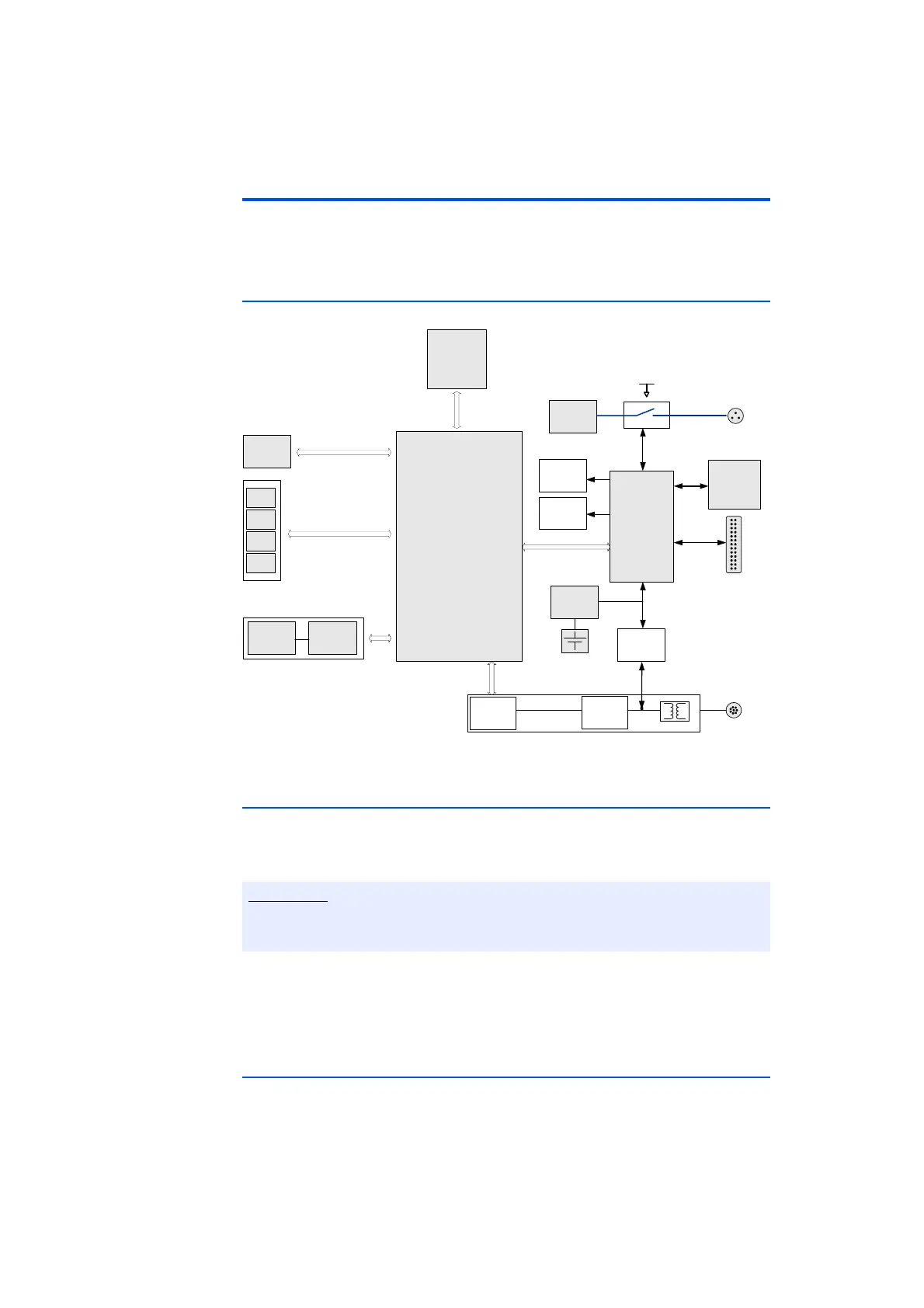
4.1 Block diagram
7‐29V
ETH
10/100MBit
CF Card
8 GB
Embedded PC
PCI CoreExpress - ECO
Intel Atom 1,6 Ghz
1 GB RAM
Power
Supply
6 - 32V
6 Front Panel
Indicator
LED’s
FrontPanelPushButton
Realtime
Clock
USB
USB
USB
USB
Antenna WLAN
Standby and
Digital I/O
Microcontroller
VGA
Ethernet
Traffic
Detection
Ethernet
Transceiver
10/100
Ethernet
Phy
26pol.SUB‐DI/O
Temperature
Sensor
Beeper
Battery
Fig. 4-1 Block diagram
4.2 Power Supply ("7-29V" Port)
The power supply interface (7-29V) of ES720.1 feeds a 2-pole plug connector
(Lemo socket) at the rear of the device. An external power supply or the vehicle
battery supply the module with current.
The ES720.1 must be physically separated from all supply voltages so that the
module will not consume any current.
When the ES720.1 is initially connected with operating voltage, the module
switches on for a few seconds. During this period, the ES720.1 is being initialized
and configured. The module acknowledges the operation with a brief acoustic
signal and waits in the operating state "Low Power Standby".
4.3 "ETH" Interface
The "ETH" interface connects the ES720.1 with ES600 modules, measuring, cal-
ibrating and rapid-prototyping modules of the measuring setup or the host PC.
 Loading...