ES720.1 - User’s Guide 29
ETAS Description of Functions
4.9 Changing between Operating States
4.9.1 Status Diagram
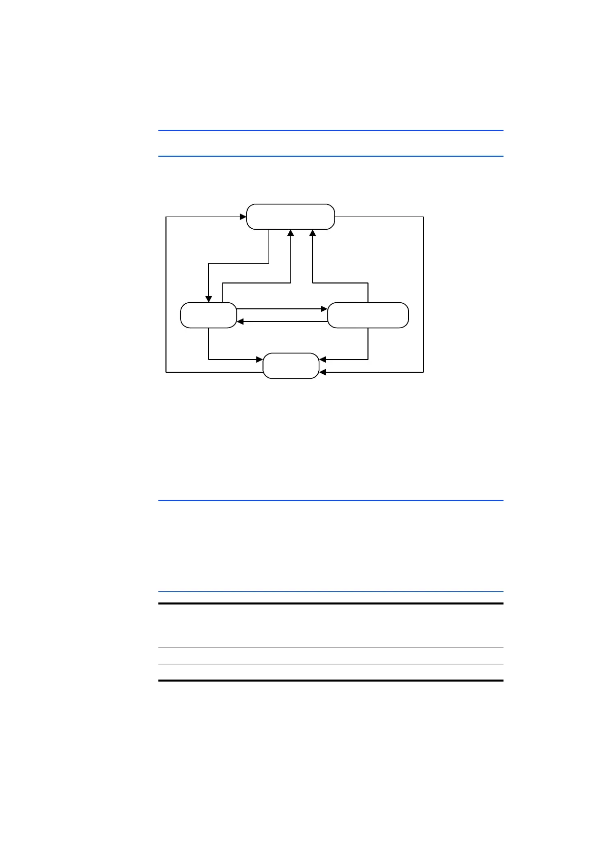
The change between the operating states can be represented in a status diagram
(see Fig. 4-2).
içï=mçïÉê=pí~åÇÄó
lå c~ëí=_ççí=pí~åÇÄó
lÑÑ
TI=UI=V
O I =P I =Q I =R
SI=TI=UI=V
NM
NNN
OI=PI=QI=R
NNNN
Fig. 4-2 Change between the operating states of the ES720.1 (simplified)
The digits in the status diagram correspo
nd to the possible operating state
changes of the ES720.1, initiated by events (trigger or timer) of the functions
"Wake-Up" and "Sleep" (see chapter 4.9.2 on page 29).
If the measurement is complete, the measu
red variables are safely stored.
Dependent on the configuration, the ES720.1 remain switched on or changes to
the operating state "Fast Boot Standby" or "Low Power Standby".
4.9.2 Events and Timers
The changes of the ES720.1 between operating states are triggered by events.
These events can be activated and deactivated in the configuration software and
combined with timers for an additional delay of the event.
The operating state changes in Fig. 4-2 on page 29 are each linked with a selec-
tion of the events and timers listed here.
General events
Event Description
No. in
Fig. 4-2
Abbrevia-
tion
1 PWR On Power supply On
11 PWR Off Power supply Off


 To Next Page