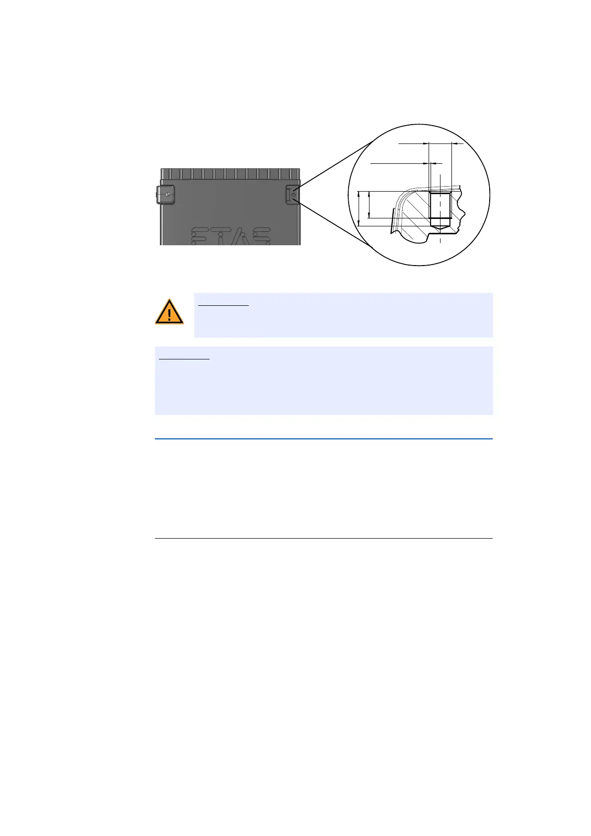
M3
0.25 x 45°
3.5
min
4.5 max
ES720.1 - User’s Guide36
Getting Started ETAS
Fig. 5-2 Tapped blind hole
Use excluding M3 cylinder screws and fastening the module onto your carrier
system with a max. torque of 0.8
Nm.
The max. length of engagement into the tapped blind hole of housing is 3 mm
(see Fig. 5-2 on page 36).
5.1.3 Connecting Several Modules Mechanically
As ETAS system housing was used, the ES720.1 can also be connected to mod-
ules of the ETAS compact line (ES59x, ES
6xx, ES910). These can be combined
easily using the T-Brackets provided to form larger blocks.
You can attach a further module of the ETAS
compact line under the ES720.1.
Just remove the four plastic feet on each of the relevant device sides and attach
the T-Brackets provided in their place.
To connect modules mechanically:
• Remove the four plastic feet from the bottom of the
ES720.1 so a further module can be attached.
This makes the assembly slits for the
T Brackets
accessible.
You can attach a further module under the
E
S720.1.
• Remove the four plastic feet on the relevant side of
t
he second module.
• Turn the seals of the T-Brackets so they are at a
r
ight angle to the longitudinal axis of the brackets
and click two brackets into the assembly slits on one
long side of the first module.
• Click the second module into the two T-Brackets.
The electronic can be damaged or destroyed!
Do not rework the threaded hole.
 Loading...