EVCO S.p.A.
EVBOX1 | Installation guide ver. 2.0 | Code 144BOX1E204
page 93 of 100
18 TECHNICAL DATA
18.1 Technical data
Purpose of the command device: operating command device.
Construction of the command device: built-in electronic device.
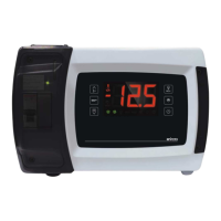
Container: grey self-extinguishing.
Heat and fire protection class: D.
Dimensions:
262.0 x 179.0 x 95.6 mm (10.314 x 7.047 x 3.763 in;
L x H x D).
Method of mounting the command device: wall mounted, with bolts and fastening screws.
Shell protection grade: IP65.
Connection method:
-
screw in terminal boards 6.35 mm pitch (0.25 in) for
wires up to 4 mm² (0.0062 in²): power supply and
digital outputs
-
screw in terminal boards 5.0 mm pitch (0.196 in) for
wires up to 2.5 mm² (0.0038 in²): analogue inputs,
digital inputs and RS-485 MODBUS port
-
screw in removable terminal board, male only
3.5 mm pitch (0.137 in) for wires up to 1.5 mm²
(0.0028 in²) or JST male only 6-way connector 2.5
mm pitch (0.098 in): driver for unipolar stepper
electronic expansion valves.
The maximum lengths of the connection cables are:
-
power supply: 100 m (328 ft)
-
analogue inputs: 100 m (328 ft)
-
transducers power supply: 100 m (328 ft)
-
digital inputs: 100 m (328 ft)
-
digital outputs: 100 m (328 ft)
-
RS-485 MODBUS port: 1,000 m (3,280 ft); please
refer also to the MODBUS specifications and
implementation guides available at
http://www.modbus.org/specs.php
-
driver for unipolar stepper electronic expansion
valves: 3 m (9.842 ft)
Use cables having a section suitable to the current running
through them.
In case of use of the device to the maximum operating
temperature and to full load, use cables having maximum
operating temperature ≥ 90 °C (194 °F).