5 HOMEDEPOT.COM
Please contact Everbilt at 1-844-883-1872 for further assistance.
Pre-Installation (continued)
DETERMINE THE DEPTH OF YOUR WELL
Tie a small but heavy weight such as a shing weight to the end of a piece of cotton string. Lower the weight into the well until it reaches
the bottom of the well. Make a mark on the string at ground level. Pull the weight out of the well and measure from the bottom of the
weight to the ground level mark. This is the depth of your well. Subtract 5 ft. from the depth of your well. If this number is less than 25 ft.
shallow well installation should be taken. If this number is more than 25 ft. and less than 70 ft. deep well installation should be taken. If
this number is more than 70 ft. a deep well submersible pump should be selected. Measure the ground level mark to the mark where the
cotton string is wetted. This number is your well’s water level. It should also be at least 10 ft. below the well’s water level while the pump
is running in order to prevent the pump from sucking air due to water level drawdown.
LOCATION OF THE PUMP
Decide on the area for the pump installation. Select a pump location with adequate space for future pump maintenance. It can be located in
the basement or utility room of the house, in a crawl space, at the well, or between the house and the well. If installed outside of the house,
it should be protected by a pump house with auxiliary heat to prevent possible freezing. Protect the pump against ooding and excess
moisture. The well also should be protected by installing a well seal for sanitary reasons. Mount the pump as close to the well as possible.
TANKS - PRE-CHARGED STORAGE
For best performance of the pump, it is recommended that you use a diaphragm pressure tank (sold separately). It is best to have this in place
before installing the pump. A pre-charged storage tank has a exible bladder or diaphragm that acts as a barrier between the compressed air
and water. This barrier prevents the air from being absorbed into the water and allows the water to be acted on by compressed air at initially
higher than atmospheric pressures (pre-charged). More usable water is provided than with a conventional type tank.
The pump has a 30/50 Psi pressure switch, which means the "cut-in" is 30 Psi; therefore, the tank needs to be set to 28 Psi. To check the
pressure in the tank, use a tire pressure gauge (not included). If the tank pre-charged less than 28 Psi, re-charge air to the tank to 28 Psi
with a tire pump or air compressor. If the tank pre-charged over 28 Psi, bleed out some air to 28 Psi.
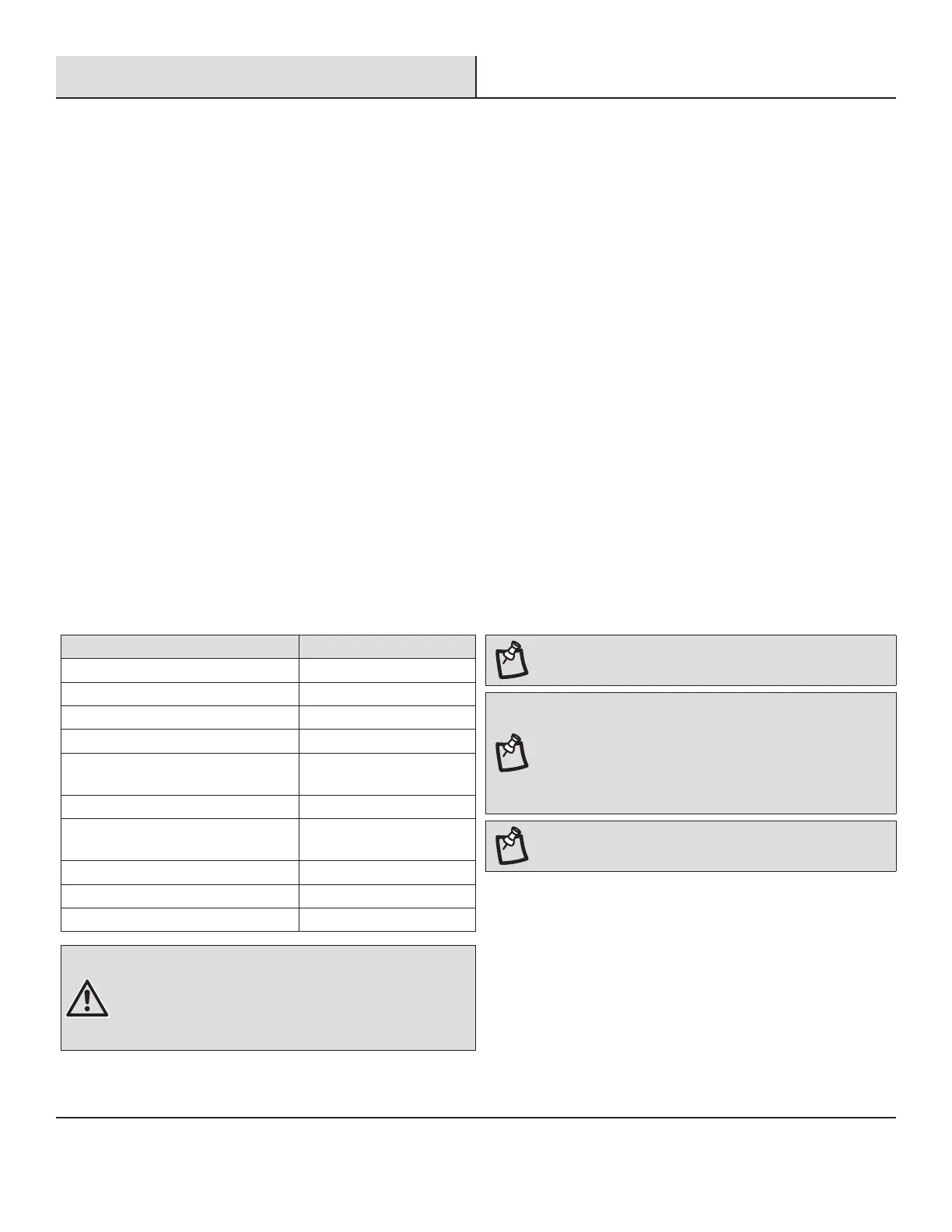
MATERIALS REQUIRED (NOT INCLUDED)
Additional items needed Size
Foot Valve 1-1/4 in.
Priming Tee 1-1/4 in.
NPT Plug 1-1/4 in.
Coupling 1-1/4 in.
PVC Pipe Schedule 80,
or PVC Pipe Schedule 40
1-1/4 in.
Coupling 1-1/4 in.
Threaded Adapter 1-1/4 in.
Male Adapter
Well Seal 4 in.
Flexible PVC Coupling 1-1/4 in.
Check Valve 1-1/4 in.
WARNING: All joints and connections must be AIRTIGHT.
A single leak will prevent the proper operation of the pump.
Wrap thread tape clockwise on all threaded connections. For all
non-threaded connections, you must use PVC Purple Primer and
PVC Cement to ensure airtight seals. Measure all pipe lengths
before attaching.
NOTE:
Either Schedule 40 or 80 pipe will work in this
installation. Be sure to check your state and local building codes.
NOTE: A foot valve is a check valve that is used to keep the
water from running back into the well from the pump and
maintain hydraulic pressure when the pump is not running.
If the foot valve does not hold the water the pump will lose it’s
prime and will not pump water. If the foot valve open pressure is
too high (the spring is too stiff), or the ow area is too small, the
pump suction head and ow rate will signicantly drop.
NOTE: The suction pipe size should not be less than 1-1/4 in.