80
Electrical System
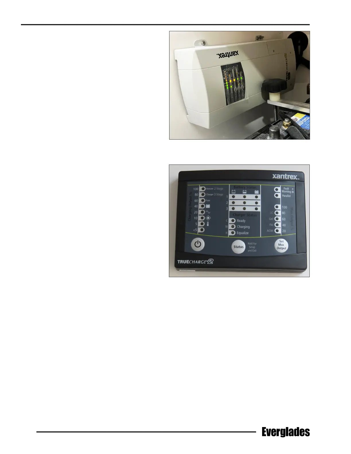
Battery Charger
The battery charger is mounted under the forward
console on the port side. AC electrical current is
supplied directly to the battery charger by a power
cable connected to a shore side GFCI outlet. The
charger automatically charges and maintains the
engine and house batteries simultaneously when
activated. It is equipped with led lights to indicate
the state of charge for each battery.
The charge to the engine batteries can be moni-
tored by using the volt meters in the engine gauge
cluster or the LED lights on the charger control
panel located on the forward head compartment
bulkhead. To monitor the engine batteries with the
volt meters in the engine gauge cluster, activate
the charger and turn the engine battery switches
on. Turn on the ignition for each engine (DO NOT
START THE ENGINES) and read the voltage on the
volt meter for each engine.
If the batteries are in good condition and charging
properly, the volt meters will indicate between 13
and 14.5 volts. If the reading is below 12.5 volts,
then the battery is not accepting a charge or the
charger is not working properly. Always turn the
ignition for both engines o immediately after
monitoring is complete when using the voltmeters
in the engine gauge cluster.
The wires that supply DC charging current to the
batteries are protected by an internal fuse in the
battery charger and external fuses, one for each
battery output wire, located near or on each bat-
tery. The external fuses protect the DC charging
circuit from the batteries to the charger. The
internal fuses in the charger protect the DC charg-
ing circuit from the charger to the batteries. See
the battery charger manual for more information.
Typical Battery Charger
Battery Charger Control Panel