33
Component Identification and Explanation
Control Panel Operation and Navigation
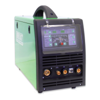
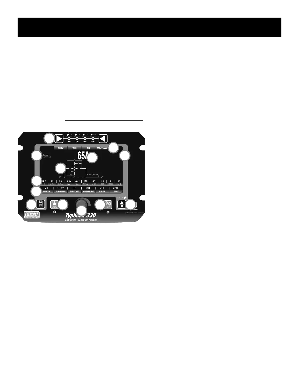
NAVIGATING THE PANEL AND SCREEN: MANUAL MODE.*
The controls of the Typhoon are simple to use. Overall navigation is fairly
intuitive with minimal clutter of keys and control knobs. When the user
interface was designed, it was important to eliminate as many hidden men-
us as possible. The number of hidden menus has been limited to one. It
requires a combination key press to access deep operating parameters that
will not be regularly adjusted. This is done to limit access by untrained or
unqualied personnel. It has been equipped with an “auto-home” function
that allows the unit to default back to the main Amp setting after 5 seconds
if no input has been made. NOTE: The manual menu screen depicted be-
low is a TIG menu, but Stick Mode is similar in adjustment and operation.
See the information below list for a basic understanding of the functions
and features of the control panel and screen:
1. Function Selector. The left and right keys allow the user to move left
or right to select between AC TIG, DC TIG, AC Stick, and DC Stick. As
the keys are pressed the LED will move to the next function. When
the function has been selected, the appropriate screen will be dis-
played and will be ready for further adjustment and navigation.
2. Save/Program Key. The Save/Program key pulls up the program
screen when pressed. When pressed in simultaneously and held
along with the Gas Purge key (#3), the hidden parameter menu will
be brought up.
3. Gas Purge Key. When pressed, the LED light will illuminate and the
gas solenoid valve will open to allow the user to set the gas flow rate
without having to trigger the torch. To stop constant gas flow, press
again and the LED will turn off and the gas flow will cease. When
pressed in simultaneously and held along with the Save/Program Key
(2#), the hidden parameter menu will be brought up.
4. Adjustment and Navigation Knob. This knob has several related du-
ties that it performs in relation to navigation, selection and adjust-
ment. It is used to navigate, select, highlight and adjust each line of
parameter (#11) and function (#12). To navigate to the parameter or
function on each line, the knob is turned clockwise or counter clock-
wise. The knob will then scroll one parameter or function for each
click the knob makes. To highlight and select the function and to
enter the adjustment mode, press the knob again. To adjust the se-
lected parameter value or selected function status, twist the knob left
or right to increase or decrease value or change function status. To
save and exit the parameter value or function status, press the knob
again, or press the up/down arrow key (#6). NOTE: By default, this
unit allows very ne, incremental adjustment while the knob is being
turned. If more rapid adjustment is needed, press and hold knob
while turning to adjust the operating parameters in larger increments.
5. PowerSet Selector. The welder has a synergic setup function called
PowerSet for rapid setup. When you select this function, a new
screen will appear. This screen will require you to input certain infor-
mation about what you are welding and it will automatically give you
useable settings for most applications. This function can assist new
hires or pro users that need a fast, simple setup process. Many func-
tions and parameters will be pre-set or have limited adjustment.
6. Up and Down Arrow Key. This key is used to navigate vertically on
the manual menu screen between the Parameter Line (#11) and the
Function Line (#12). When using the PowerSet function, it is used to
scroll both horizontally and vertically through the user input settings.
In this mode, each separate press of the key navigates to the next set
of user input data and readies the welder for more user data input and
adjustment. The key navigates vertically on the left column then navi-
gates to the right column and nally across the bottom Function Line.
7. Screen Information and Status Bar. The upper information and status
bar is available in both the Manual and PowerSet mode screens. This
bar is designed to conrm and remind the user of the welding modes,
and operating voltage of the machine. The operating voltage indicator
serves both as a reminder and as a diagnostic tool, in case the ma-
chine is not sensing 240V because of faulty input wiring.
8. The Parameter Value Display Area. In Manual setup mode, the area at
the top of the screen with the large, white numbers and letters always
reflects the value of the parameter or function that has been selected
for adjustment. If a parameter is selected for adjustment, it will in-
clude type of value being displayed as well as well. For example, for
the example if the parameter value is 65, the screen may display the
value as Percent (%), Hertz (Hz), Amps (A), or Seconds. Wave Form
parameters are the only non-numeraled parameter that will be dis-
played on the Parameter Line (#11). In the case of the Function Line
(#12) the function itself will be displayed in an expanded less abbre-
viated form when it is selected and adjusted.
9. Polarity Reminder/Volt Readout. The Polarity reminder is in the upper
left corner to remind the user to check and use the polarity that is
listed. 9a: In stick mode the unit also displays OCV and weld voltage
1
2 3
4
5 6
7
8
9
10
11
12
9a
 Loading...