Design and function
Plasma welding
099-004854-EW501
19.02.2014
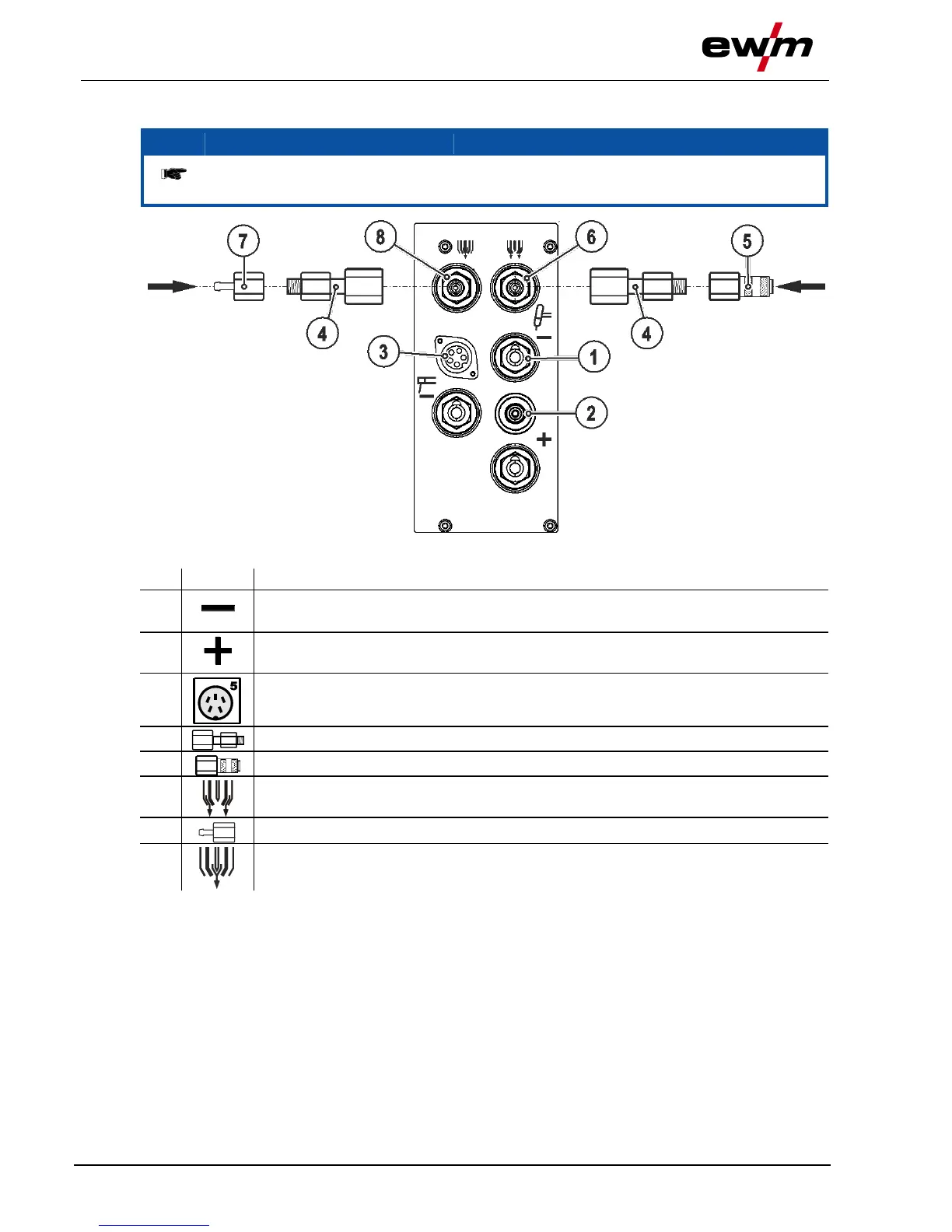
5.7.2 Welding torch connection (no gas metering unit GMU)
Before commissioning, the plasma welding torch must be equipped for the welding JOB
and correspondingly set/adjusted!
Connection socket, "-" welding current
TIG/Plasma welding current connection
Pilot current connection socket
Plasma welding torch nozzle potential
5-pole connection socket, welding torch control lead
G1/4" shielding gas connecting nipple, welding machine output
Connection to the welding torch or gas metering unit (GMU)
Adapter (G1/8 > plug-in nipple)
G1/4" plasma gas connecting nipple, welding machine output
Connection to the welding torch or gas metering unit (GDE)
• Insert the plug on the welding current lead into the "-" welding current connection socket and lock.
• Insert the plug of the pilot power line into the "+" pilot current connection socket.
• Insert the torch control lead plug into the “5-pole connection socket, welding torch control lead” and
lock.
• Screw adapter (G1/4 > G1/8) onto G1/4 shielding gas connecting nipple, welding machine output.
• Screw adapter (G1/8 > cap) onto adapter (G1/4 > G1/8).
• Insert connecting nipple on the torch shielding gas line into adapter (G1/8 > cap).
• Screw adapter (G1/4 > G1/8) onto connecting nipple (G1/4, plasma gas connection).
• Screw adapter (G1/8 > plug-in nipple) onto adapter (G1/4 > G1/8).
• Insert connection socket on the torch plasma gas line onto adapter (G1/8 > plug).