Do you have a question about the EWM Tetrix 351 and is the answer not in the manual?
Guidelines for safe usage, hazard warnings, and general precautions.
Explains various symbols used in the manual to convey specific meanings and instructions.
Instructions and warnings related to safely moving and setting up the welding machine.
Details various welding processes supported, including TIG variants and MMA.
Lists applicable documents, warranty, conformity, and requirements for hazardous environments.
Provides a general overview of the integrated welding system components and their arrangement.
Explains fundamental safety and operational principles related to electrical shock, burns, and moving parts.
Details the importance of ventilation, air inlets/outlets, and preventing contamination for optimal cooling.
Instructions for connecting workpiece leads and welding current leads to ensure proper function and prevent faults.
Specifies the necessary conditions and precautions for connecting the machine to the public mains network.
Outlines the types of coolants, maximum hose lengths, and procedures for adding coolant.
Covers the importance of proper gas supply and connection procedures for optimal welding results.
Introduces TIG welding, including cold and hot wire techniques, and specific connection plans.
Details the connection plan and installation procedures for TIG hot wire welding systems.
Explains how to configure the machine for mechanical arc fusion welding using the Expert menu.
Guides on connecting the welding torch, hose package, and workpiece line for TIG welding.
Explains the synergistic operating principle, key parameters, and how to select welding tasks.
Details how to set torch modes and adjust up/down speed for different torch types and functions.
Explains operation for standard TIG torches with one or two torch triggers, detailing functions and modes.
Details operation for TIG up/down torches (8-pole) with one torch trigger, including functions and modes.
Explains operation for potentiometer and RETOX torches, covering their functions and modes.
Explains how to set maximum JOBs and the first increment, relevant for specific torch modes.
Explains the meaning of hazard keywords (DANGER, WARNING, CAUTION) and associated warning symbols.
Highlights specific technical points and step-by-step actions that users must observe for correct operation.
Provides a comprehensive list and explanation of symbols used throughout the operating instructions.
Details critical safety measures to prevent electric shock, including handling live parts and capacitor discharge.
Warns about electromagnetic fields and emphasizes that only skilled personnel should perform repairs.
Stresses observing safety instructions to prevent injuries and advises on protection against arc radiation and burns.
Warns about explosion risks, hazards from smoke/gases, and fire risks from welding processes.
Highlights dangers of coupling multiple power sources and advises on hearing protection from noise.
Outlines operator responsibilities, directives, and EMC classification of machines for intended use areas.
Warns against using non-genuine parts and the damage caused by stray welding currents.
Explains mains connection requirements and provides recommendations for minimizing electromagnetic interference.
Classifies machines by EMC standards and offers recommendations for reducing interference emission.
Provides guidance on setting up and operating to minimize electromagnetic interference and reduce emissions.
Includes warnings about gas cylinder handling, tipping risks, and damage from disconnected supply lines.
Emphasizes that units are designed for upright operation to prevent equipment damage.
Details critical safety measures and hazards associated with lifting the machine or system components by crane.
Warns about the risks of using damaged or unsuitable lifting eyes and how to check them.
Specifies requirements for the installation site, including stability, level base, and ambient conditions to avoid damage.
Defines the operational and storage temperature and humidity ranges for the machine.
Warns about hazards arising from improper or incorrect usage of the equipment and liability.
Describes various TIG welding applications such as hot wire, cold wire, activArc, spotArc, and Spotmatic.
Explains MMA welding, characterized by the arc burning between a melting electrode and the molten pool.
Lists machines compatible with TIG hot wire and TIG cold wire processes, indicating possible or impossible combinations.
Refers to warranty information and the Declaration of Conformity for EC Directives and standards.
Emphasizes that only skilled persons should perform repairs and that warranty is void with unauthorized modifications.
Provides a general overview of the integrated welding system components and their arrangement.
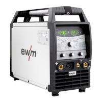
Shows a diagram of the front view of the Tetrix 351 AC/DC AW welding machine with numbered components.
Identifies and describes components visible on the front panel of the welding machine, including connection sockets and controls.
Displays a diagram of the rear view of the Tetrix 351 AC/DC AW welding machine, indicating numbered components.
Identifies and describes components located on the rear panel of the welding machine, including connection sockets and interfaces.
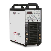
Illustrates the front view of the Tetrix 451, 551 AC/DC AW welding machines with numbered components.
Lists and explains the components visible on the front panel of the Tetrix 451 and 551 AC/DC AW welding machines.
Shows a diagram of the rear view for the Tetrix 451, 551 AC/DC AW welding machines with numbered components.
Identifies and describes components on the rear panel of the Tetrix 451 and 551 AC/DC AW welding machines.
Explains buttons for polarity changeover and selecting welding processes (MMA, TIG Synergic, TIG Manual).
Details buttons for tungsten electrode diameter, seam type selection, and operating mode.
Describes buttons for pulsing, synchronization, error indicators, and parameter setting.
Explains status displays and parameter selection buttons for functions like gas pre-flow and current settings.
Details settings for secondary current, pulse times, down-slope, AC balance, frequency, and activArc activation.
Provides critical safety instructions to prevent electric shock, burns, and injury from moving parts.
Warns about risks from escaping welding wire and electrical current exposure when using multiple methods.
Highlights dangers of incorrect connections for accessories and workpiece leads, and the importance of protective caps.
Provides guidelines for routing workpiece leads and hose packages to prevent arc flickering and HF sparkover.
Illustrates correct methods for using individual welding leads, unrolling leads, and managing excess cable length.
Details safety hazards of improper mains connection and requirements for three-phase systems.
Warns against coolant mixtures, emphasizes frost protection checks, and lists coolants and hose lengths.
Provides instructions for adding coolant, checking the filter sieve, and ensuring the coolant level is maintained.
Highlights risks of improper cylinder handling and issues with shielding gas supply, emphasizing gas-tight connections.
Details fastening gas hose, setting gas quantity, and performing gas tests for TIG welding.
Details connecting the gas hose nipple for TIG cold or hot wire welding.
Illustrates the connection plan for TIG cold wire welding systems, showing component interconnections.
Explains connection symbols and specifies installation site requirements for TIG cold wire welding.
Details the connection of the intermediate hose package for TIG cold wire systems, showing component identification.
Provides step-by-step instructions for connecting various components of the TIG cold wire system, including plugs and couplings.
Illustrates the connection plan for TIG hot wire welding systems, showing how different components are interconnected.
Explains the symbols used in the connection diagrams for TIG hot wire welding systems.
Details the installation process for the wire feed unit, including safety warnings about falling.
Explains the procedure for mounting the hot wire power source onto the carrier platform, including safety notes.
Provides safety information and instructions for connecting the hot wire power source to the primary power source.
Details the connection of the intermediate hose package for TIG hot wire systems, showing component identification.
Provides step-by-step instructions for connecting the wire feed unit, control lead, cooling tubes, and shielding gas for hot wire systems.
Explains the initial configuration steps in the Expert menu, including activating filler wire and selecting hot/cold wire processes.
Describes how to navigate the Expert menu using buttons and the rotary dial for parameter adjustment.
Explains how to set filler wire diameter and adjust wire return values, noting manual versus correction modes.
Guides on selecting welding tasks using the JOB list based on material, electrode, and seam position.
Details the two wire speed operating modes: MANUAL (absolute value) and CORRECTION (percentage).
Explains how to set welding current on the machine and wire speed using different operating modes.
Introduces function sequences and operating modes, defining symbols used for torch triggers and processes.
Provides a legend for symbols representing torch trigger actions and various welding parameters/states.
Details the step-by-step operation of the non-latched mode, including current and wire feed cycles.
Explains the differences in wire feeding for 3-cycle and latched modes, and how to use tapping start.
Provides guidance and cautions on connecting the welding torch, hose package, and workpiece line for TIG welding.
Details various TIG torch connection socket types and their corresponding pin assignments for control and welding current.
Explains the TIG Synergic operating principle, including key parameters like electrode diameter, material type, and seam type.
Details how synergistic parameters are adjusted automatically, with options for conventional setting.
Explains how conventional parameters can be adjusted independently of welding current, utilizing basic parameters.
Guides on how to set the operating principle between synergic (on) and conventional (off) modes via the machine control.
Explains how to select the welding task using machine buttons, including conditions for parameter changes.
Describes two methods for setting welding current: via sheet metal thickness or directly as welding current.
Explains the parameters displayed before, during, and after welding, including nominal, actual, and hold values.
Details how welding currents (ignition, secondary, end, hotstart) can be displayed as percentages or absolute values.
Explains how to enter, navigate, and exit the Expert menu for TIG parameters like slope times and activArc.
Describes the process of setting welding parameters and how the right-hand display shows factory settings or adjustments.
Explains the HF ignition and Liftarc ignition methods for starting the welding arc.
Describes the automatic cut-out function triggered by ignition faults or arc interruptions.
Explains how to adjust a parameter to improve ignition characteristics for pure tungsten electrodes.
Details selecting AC/DC welding materials and the tungsten balling selection process.
Introduces function sequences and explains symbols for selecting parameters and using the rotary transducer.
Details the steps and conditions for operating in the non-latched mode, including current and wire feed cycles.
Details the steps for latched mode operation, including how to switch between main and secondary currents.
Explains the SpotArc process for tack welding, its operating modes (long/short interval), and related settings.
Details the SpotArc process sequence and lists available pulse variants for TIG DC and TIG AC.
Describes the Spotmatic process, its activation modes, and selection/adjustment procedures.
Explains the non-latched operation mode, version C, detailing its specific cycles and activation requirements.
Introduces pulse welding, explaining how sequences behave and how pulse functions can be deactivated.
Details TIG pulse operation in both non-latched and latched modes, illustrating current and time cycles.
Explains thermal pulses, including setting pulse time, break time, and slope times in seconds.
Details kHz pulses (metallurgic) and automated pulses, including balance, frequency, and machine-specified parameters.
Describes AC pulse and AC special modes, outlining their applications and parameter definitions.
Explains the activArc process for maintaining constant power, preventing electrode sticking, and reducing inclusions.
Describes the antistick function that prevents electrode sticking by switching off welding current.
Introduces different torch versions and how functions can be modified via torch modes, including the tap trigger function.
Details available torch modes (1-6, 11-16) and how to set up/down speed for current change.
Explains operation for standard TIG torches with one or two torch triggers, detailing functions and modes.
Describes operation for MG rocker torches with two torch triggers, detailing functions and modes.
Explains operation for TIG up/down torches (8-pole) with one torch trigger, including functions and modes.
Details operation for 8-pole TIG up/down torches with two triggers, covering various functions and modes.
Explains operation for potentiometer torches (8-pole) with one or two torch triggers, detailing functions and modes.
Provides safety warnings and instructions for configuring the potentiometer torch connection, including jumper settings.
Details the operation of the RETOX TIG torch (12-pole), including various modes and functions like JOB switching.
Explains how to set the maximum number of JOBs accessible, relevant for specific torch modes.
Describes how to set the first increment value, applicable to up/down torches in specific modes.
Highlights safety measures for MMA welding, including risks of burns and proper handling of electrodes.
Details the connection process for the electrode holder and workpiece lead to the welding current sockets.
Guides on selecting the MMA welding process and setting the welding current.
Explains the function for electronically reversing welding current polarity, useful for different electrode types.
Details how to select and adjust welding current polarity (DC-, DC+, AC) for MMA welding.
Explains how to set frequency and balance for alternating current (AC) welding in MMA.
Describes the hotstart device for improving electrode ignition using increased ignition current.
Details setting hotstart time and explains the arcforce function to prevent electrode sticking.
Describes the antistick function that prevents electrode overheating by switching to minimum current if sticking occurs.
Details characteristics and settings for MMA pulse welding in the vertical up (PF) position, suitable for root welding.
Explains that the machine has 16 programs, which can be changed during welding, and how parameters are saved in JOBs.
Guides on selecting and adjusting welding programs using the machine control, including setting operating modes and welding current.
Explains how to limit the number of accessible programs, useful for specific torch types.
Provides examples of programs and lists accessories for program management.
Explains the JOB Manager for loading, copying, and saving welding tasks (JOBs), defining what a JOB consists of.
Defines the symbols used in the JOB Manager for operations like Load JOB, Copy JOB, Reset JOB, and Reset All JOBs.
Guides on copying pre-defined welding tasks from fixed memory to free memory or creating new JOBs.
Details loading existing JOBs and resetting specific JOBs to factory default settings.
Explains how to reset all JOBs from 1 to 128 to their factory settings.
Explains how to exit the JOB Manager without saving any changes made.
Describes manual remote controls and their functions for adjusting welding current and other parameters.
Details specialized manual remote controls for SpotArc, AC welding, and potentiometer torches.
Describes the functions of foot-operated remote controls for start/stop and current adjustment, noting incompatibility with ActivArc.
Explains how to activate and deactivate the ramp function for foot-operated remote controls RTF 1 / RTF 2.
Explains the importance of simultaneous welding and synchronization via mains voltage to avoid arc interference.
Describes synchronisation via cable (master/slave operation) using the SYNINT X10 interface and extension cables.
Details the pin assignments and functions of the TIG interface for mechanised welding, including signal types and designations.
Explains the pin assignments and functions of the 19-pole remote control connection socket for various inputs and outputs.
Explains using a key switch to lock parameters and warns about PC interface connection safety.
Guides on how to enter, navigate, and exit the machine configuration menu using buttons and the rotary dial.
Presents a flowchart illustrating the structure and navigation within the machine configuration menu.
Lists and explains various parameters within the configuration menu, such as torch modes, operating principles, and pulse settings.
Details advanced settings like ramp functions, tungsten balling, polarity switching, and spotArc/Spotmatic modes.
Explains automation settings, service menu access, reset functions, and software version queries.
Explains how to set the ignition pulse limit parameter within the machine configuration menu.
Guides on aligning cable resistance to ensure optimum welding properties, involving voltage correction.
Provides step-by-step instructions for the cable resistance alignment process, including preparation and measurement.
Explains how to activate and deactivate the power-saving mode, and how it affects machine displays.
Emphasizes repair safety, warns against electric shock during cleaning, and provides general maintenance advice.
Outlines daily tasks including visual inspection of leads and torch, and functional tests of controls.
Lists visual inspection and functional test tasks to be performed monthly on the machine and torch.
Details requirements for annual inspection and testing by competent persons, adhering to standards and local regulations.
Instructs on proper disposal, recycling, and manufacturer declarations regarding regulations and RoHS compliance.
Provides a checklist for troubleshooting common faults related to coolant, function errors, connections, and torch overheating.
Addresses common issues with wire feed systems, including contact tip problems and pore formation due to gas shielding.
Lists common power source warnings, their possible causes, remedies, and how to reset them.
Details error messages from Err 3 to Err 19, their potential causes, and troubleshooting steps.
Continues the list of power source error messages, their causes, and remedies, including coolant and electronics errors.
Explains how to reset all customized welding parameters back to the factory default settings using the menu.
Guides on querying the software version of the machine control for service staff.
Warns about the function of external interrupt equipment (emergency stop) via the automated welding interface.
Provides instructions on how to vent the cooling system, emphasizing the use of the blue coolant connection.
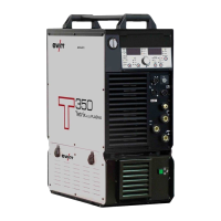
Lists detailed technical specifications for the Tetrix 351 AC/DC AW welding machine, including current, voltage, duty cycle, and dimensions.
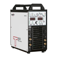
Provides detailed technical specifications for the Tetrix 451 AC/DC AW welding machine, covering electrical, mechanical, and environmental data.
Lists detailed technical specifications for the Tetrix 551 AC/DC AW welding machine, including current, voltage, duty cycle, and dimensions.
Lists system components like wire feed units and hot wire power sources with their respective item numbers.
Lists optional accessories available for the Tetrix 351 AC/DC model, such as air filters and gas bottle holders.
Lists optional accessories for Tetrix 451 and 551 AC/DC models, including air filters and gas bottle holders.
Lists optional accessories for multiple Tetrix models, including connection sockets, holders, and key switches.
Lists general accessories such as coolants, frost protection testers, pressure regulators, and gas hoses with item numbers.
Lists various remote controls and associated cables for different welding torch types and functions.
Lists accessories for computer communication, including welding parameter software and interface cables.
Presents a table listing JOB entries, detailing process, material, wire, seam position, and tungsten electrode diameter.
Continues the JOB list, specifying process, material, wire, seam position, and tungsten electrode diameter for various materials.
Continues the JOB list, detailing process, material, wire, seam position, and tungsten electrode diameter for various materials.
Completes the JOB list, including advanced settings, special customer orders, and test jobs.
Lists EWM branches and their contact information across Germany and internationally.
| Mains voltage | 3 x 400 V |
|---|---|
| Mains frequency | 50 / 60 Hz |
| Mains fuse (slow-blowing) | 16 A |
| Open circuit voltage | 70 V |
| Protection class | IP23 |
| Welding process | MMA, TIG |