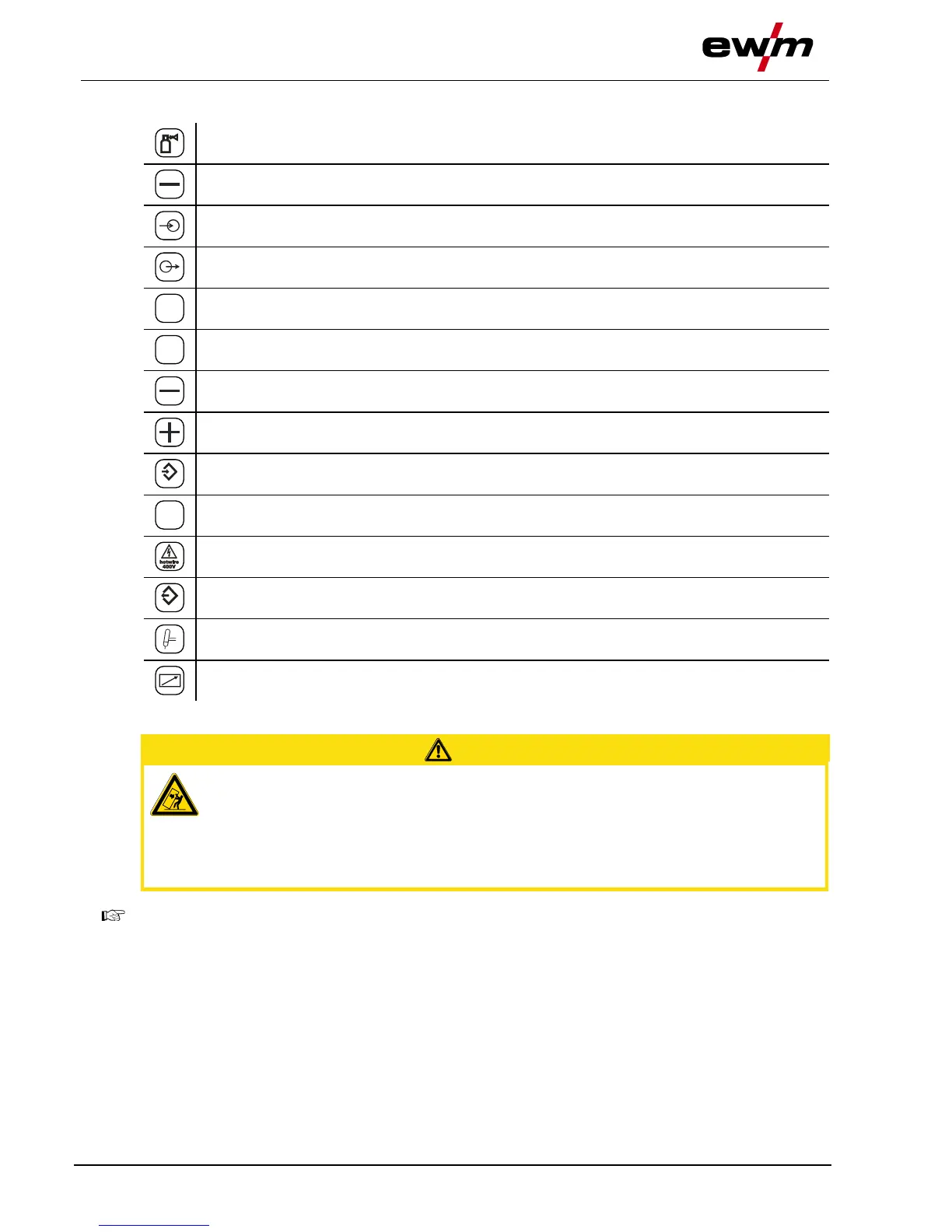
Design and function
TIG cold wire welding
099-000115-EW501
17.06.2015
Welding current(minus potential)
Coolant input (marked in colour)
Coolant output (marked in colour)
Hose package (TP = tube package)
Welding current (minus potential, TIG hot wire)
Welding current (plus potential, workpiece)
Control lead, hot wire (signal input, 4-pole)
Connection, supply voltage (3-phase)
Supply voltage, hot wire power source
Control lead, hot wire (signal output, 4-pole)
Control lead, welding torch (12-pole)
Remote control connection
Installation site!
The machine must not be operated in the open air and must only be set up and
operated on a suitable, stable and level base!
• The operator must ensure that the ground is non-slip and level, and provide sufficient
lighting for the place of work.
• Safe operation of the machine must be guaranteed at all times.
In a TIG cold wire welding system the wire feed unit is placed onto the casing cover of the TIG
power source.