Design and function
TIG Synergic operating principle
099-000115-EW501
17.06.2015
5.13.10 Function sequences/operating modes
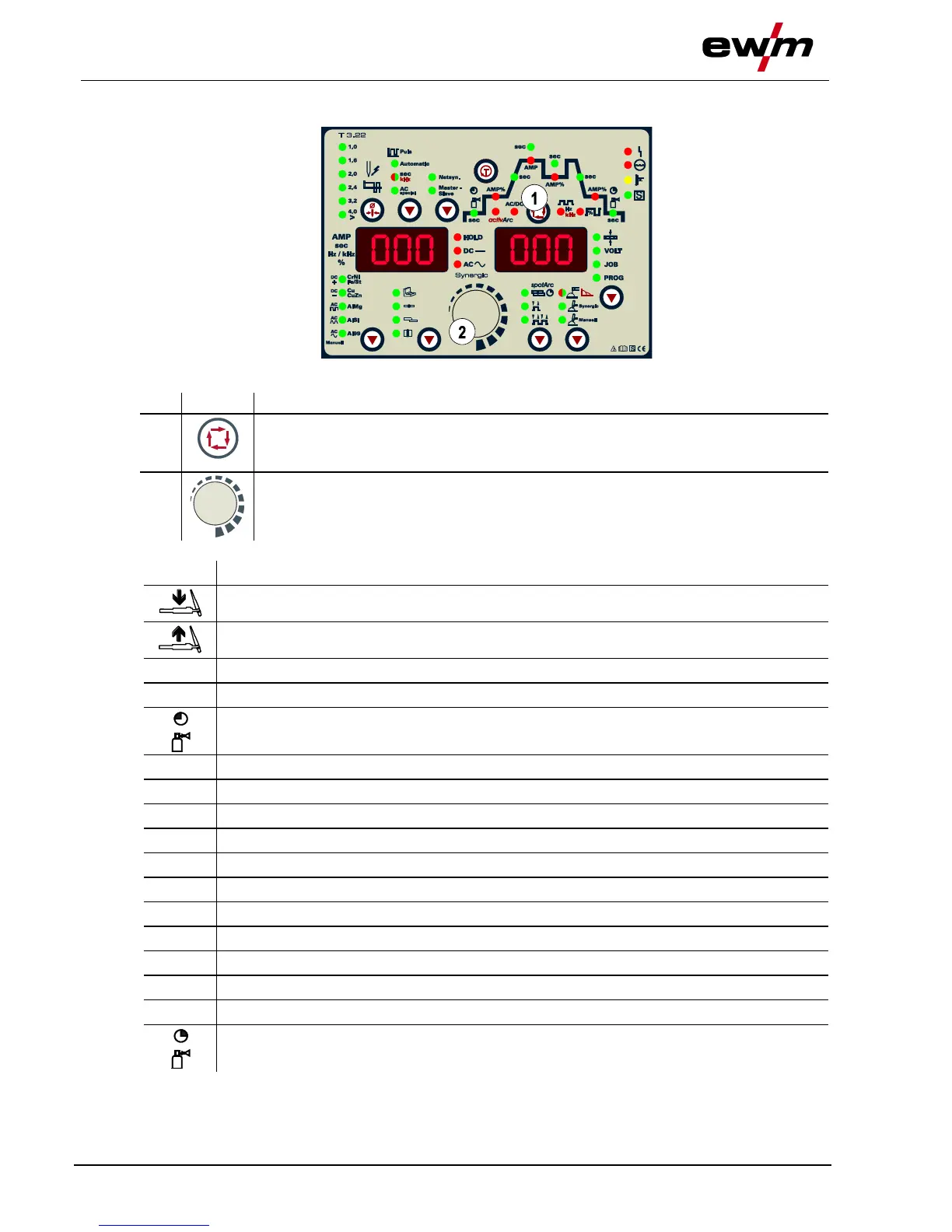
Figure 5-29
Select welding parameters button
This button is used to select the welding parameters depending on the welding process
and operating mode used.
Welding parameter setting rotary transducer
Setting of all parameters such as welding current, sheet metal thickness, gas pre-flow
time, etc.
5.13.10.1 Explanation of symbols
Main current (minimum to maximum current)
Secondary current (0% to 100% of AMP)
TIG pulses: Slop time from main current (AMP) to secondary current (AMP%)
TIG pulses: Slop time from secondary current (AMP%) to main current (AMP)