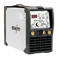
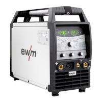
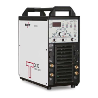
Machine description – quick overview
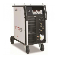
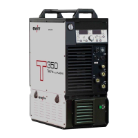
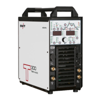
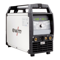
Front view
099-000115-EW501
17.06.2015
Main switch, machine on/off
Machine control- See 4.8 Machine control – Operating elements chapter
Automatic cut-out of coolant pump key button
press to reset a triggered fuse
Quick connect coupling (red)
coolant return
Quick connect coupling (blue)
coolant supply
Connection socket, 8-pole/12-pole (depending on variant)
8-pole: Control cable TIG up/down or potentiometer torch
12-pole: Control cable TIG up/down torch with LED display (option)
Connection socket, 5-pole
Standard TIG torch control lead
G¼“ connecting nipple, welding current "-" (with DC- polarity)
Shielding gas connection (with yellow insulating cap) for TIG welding torch
Connection socket, welding current “-” (with DC- polarity)
connection TIG welding torch
Connection socket, welding current “+” (with DC- polarity)
Connection for workpiece lead
Key switch for protection against unauthorised use
Position “1” > changes possible,
Position “0” > changes not possible.
- See 5.20 Protecting welding parameters from unauthorised access chapter
Connection socket, 19-pole
Remote control connection
Connection socket, welding current “-” (with DC- polarity)
connection for Electrode holder
Operating state signal lamp
Lights up when the machine is ready for use.