16
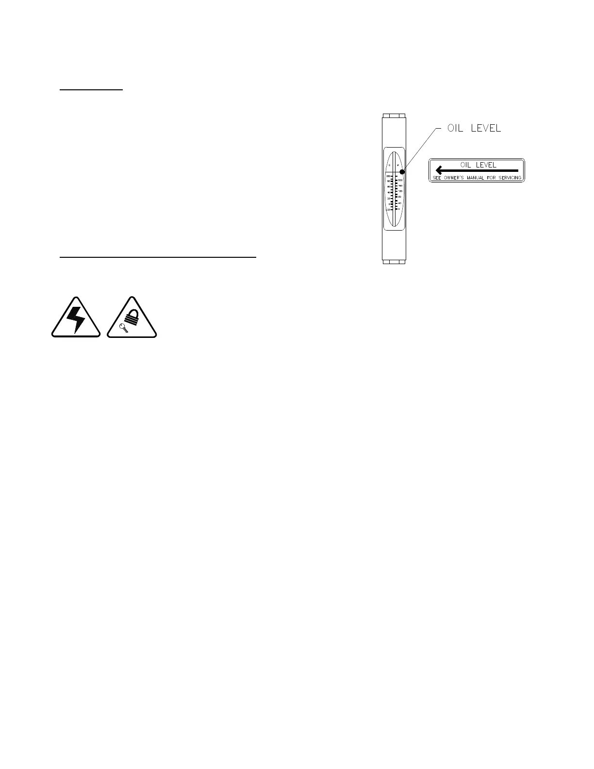
HYDRAULICS Diagram E. Temperature/Sight
Gauge
The hydraulic system has been completely operated and tested
at the factory. Check all hydraulic connections to insure that no
leaks have developed during transit.
Check the oil level within the reservoir. The oil in the
temperature/sight gauge on the side of the reservoir
should be even with the oil level arrow when the platen
is fully retracted.
CONNECTING BALER TO POWER SOURCE
All wiring must be in accordance with local and national electrical code regulations.
Observe proper Lock Out/Tag Out procedures before connecting power to the baler. Make sure
that the MAIN disconnect switch is padlocked in the OFF position. Place an appropriate warning
tag , “UNDER REPAIR, DO NOT USE,” on the switch so it will not be energized without notifying
the person making wiring connections.
See the APPENDIX section of this manual for the wiring diagram and electrical schematic. A copy of the wiring diagram and electrical
schematic may also be enclosed inside the print pocket of the electrical enclosure.
1. Open the electrical enclosure. Refer to Diagram F for operation and lock out procedure of the BALER power disconnect. Also,
refer to LOCK OUT/TAG OUT PROCEDURE section of this manual.
Diagram F. Operating and Lockout Procedure of Baler Power Disconnect.