39
LIMIT SWITCH ADJUSTMENTS
Tools Required:
1/2" Wrench
Before proceeding, make sure that the six inch long limit switch cam is set flush with the left end of the slide that it is mounted on. Also
check to see that the limit switch arms are at right angles (90 degrees) to the switch bodies.
Adjustment of the switches is made by loosening the nuts which hold the limit switch mounting angles to the aluminum housing. When
retightening, do not over tighten these nuts, or the aluminum housing will be distorted.
NOTE: The tie-off switch has a special one-way action and is not interchangeable with the front, rear or short stroke limit switches.
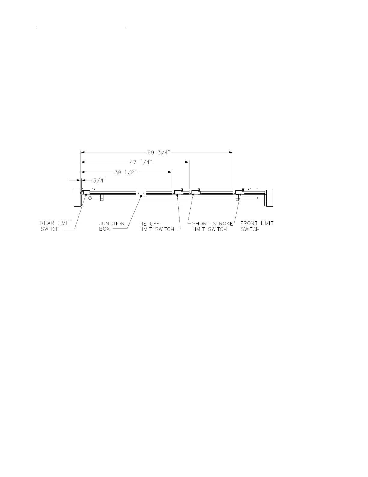
Refer to Diagram N to make these adjustments.
Diagram N. Limit Switch Adjustment Diagram.
REAR LIMIT
The rear limit switch is 3/4" from the left end of the aluminum housing to the edge of the limit switch mounting angle. This should stop
the ram 1 1/2" to 2" from the end of its stroke.
This may be checked by temporarily removing the limit switch. Allow the cylinder to "Bottom Out" and take a measurement to be
compared with a measurement taken after the switch is adjusted. The difference should be 1 1/2" to 2".
TIE-OFF LIMIT
Adjustment of this switch will affect the size of the finished bale. The 41 1/4" measurement shown in the diagram will produce
approximately a 48" bale. It is not possible to tie off bales larger than 48". If a smaller bale is desired, move the switch to the right.
This will increase the 41 1/4" measurement, which should not exceed 45 1/2". Any adjustment made to the tie off limit should also
be equally made to the short stroke limit.
SHORT STROKE LIMIT
To maintain 8” of chamber penetration, the short stroke limit switch is 49” from the left end of the aluminum housing.