18
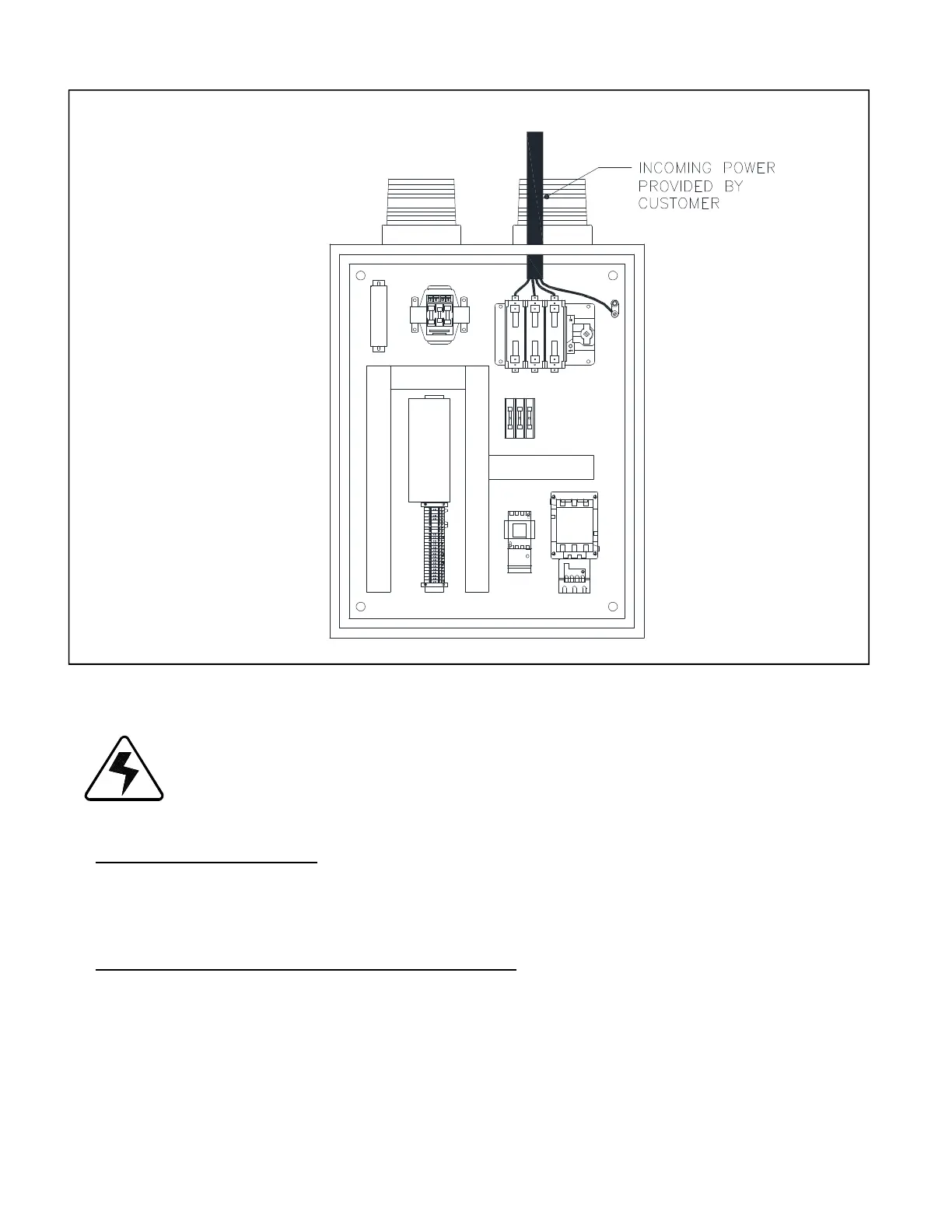
Diagram G. Connecting Electrical Power to Disconnect Inside Box.
5. Close the electrical box.
Do not close the MAIN power supply switch or turn the handle to ON until instructed to do so in the START UP
AND TESTING section of this manual.
REMOVE ATTATCHED PARTS
Open baler door and remove clean out tool from inside tube at top front of chamber. Remove the grease gun attatched to inside of bale
door.
WIRE GUIDE INSTALLATION (INSTALLED AT FACTORY)
Parts Required: EX2001-2424
6 - Wire Guides 12 – P-1016 Bolts
12 – P-1025 Flat Washers
12 – P-1024 Lock Washers
OR
EX 2425 & above
Studs 12 – P-1023 Nylock Nut
12 - P-1024 Flat Washer