EX-2001 NC RACER ZSME300000091
22
EXCELL PRECISION CO., LTD.
DATA OUT
REAR PANEL
1
23
4
5
98
76
4
32
1
89
76
5
CHAPTER 7 INTERFACES
7-1 OP-01 RS-422 & RS-485 INTERFACE
2
OP-01 RS-422 / RS-485
With this interface up to 10 indicators can be connected together and data transferred to a
host controller.
FUNC. 70 should be set to “ 1 ”
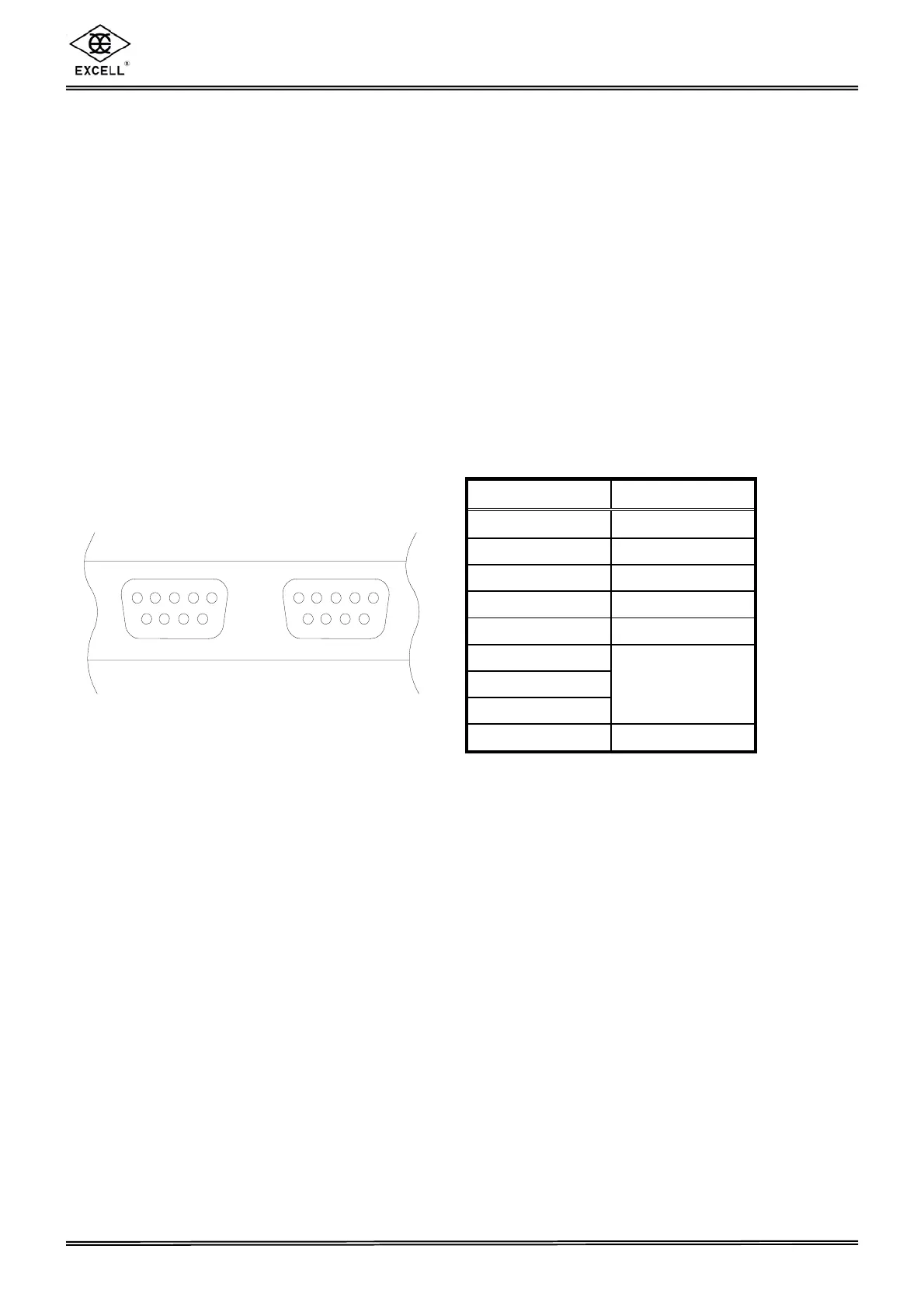
2 Connector pin assignment
Pin number Function
1
T+ / DA
2 T - / DB
3 R+
4 R -
5 TRM
6
7
8
FG
9 RDB’
Remark:
♦ The host computer has a built-in terminator. The host computer does not have signal
ground (SG).
♦ When RS-422 is transferred to RS-485, Pin1, 3 (short) and Pin 2, 4 (open).
♦ When connecting the last EX-2001 indicator, the fifth Pin (TRM) and the ninth Pin
(RDB’) should be connected together.
REAR PANEL
DATA
OUT
 Loading...