Do you have a question about the Excell 320S and is the answer not in the manual?
Essential safety measures for installation and operation of the instrument.
Highlights the key capabilities and applications of the 320S indicator.
Lists the optional interface modules for serial, BCD, and analog outputs.
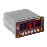
Details the front panel display, indication icons, weighing units, and USB indicator.
Describes the rear panel terminal block, RJ45 port, and operational switches.
Provides guidance on controlling and eliminating electrostatic interference in industrial environments.
Explains the function of each key on the front panel during operation and setting.
Details sensitivity, sampling speed, application range, and load cell excitation.
Outlines power requirements and physical dimensions of the indicator.
Guides on entering calibration mode, function setting, and parameter resets.
Illustrates the sequence for configuring serial and parallel output interfaces.
Details configuration steps for external parallel, IP address, port, Modbus, USB logger, and RTC.
Lists and describes various function parameter codes (FnC) for device configuration.
Details parameters for Digital Filter I, Digital Filter II, and Key Lock functions.
Explains the settings for the "F" and "F1" function keys, including batching and hold modes.
Configures how various statuses are displayed on the front panel.
Sets return-to-zero band parameters and hold mode configurations.
Details settings for turn-on zero, stand-by mode, zero record, and internal calibration password.
Describes how to test the MODBUS TCP/IP connection using a ping command.
Guides on using a web browser to configure serial port settings for the 320S indicator.
Details how to use MODBUS Poll software to connect and configure the device.
Lists and explains common error messages encountered in general function settings.
Explains how to set, change, or remove the internal calibration password.
Illustrates the connection diagram for a 4-wire load cell and pin assignments.
Provides a flowchart for parameter setting and the overall calibration process.
Details steps for initiating MODBUS, Specification, General, and Linearity calibrations.
Outlines the procedure to start the Digital Calibration process.
Explains how to perform MODBUS calibration for zero and span settings.
Lists parameter codes for specification calibration, including Unit, Decimal Point, and Max. Capacity.
Details parameters for Unit, Decimal Point, and Division size in specification calibration.
Covers Max. Capacity, Zero Range, Time/Range of Zero Tracking, and stability settings.
Guides on performing Zero Calibration and Weight Calibration for general calibration.
Details the steps for performing linearity calibration, including setting values and points.
Explains how to display the setting values for linearity calibration.
Guides on clearing the setting values for linearity calibration.
Outlines the steps for digital calibration, including zero and span voltage inputs.
Lists item codes and their descriptions for the function configuration menu.
Details parameters for Batching Mode, including normal, loss-in-weight, and hold modes.
Covers parameters for batch start delay, waiting time, and batch finish conditions.
Details parameters for batch finish output signal and supplementary loading.
Covers discharge start/stop delay, TARE auto, Hi/OK/Lo settings, and weight comparison delay.
Guides on configuring Final, Under, SP1, and SP2 values for check weighing.
Details setting Hi, Lo, and Zero Band values for check weighing in comparison mode.
Covers setting Hi, Lo, Zero Band, and Peak Ready values for hold mode check weighing.
Describes output conditions for SP1, SP2, SP3, Under, Over, and Zero Band in normal batching.
Explains signal outputs for loss-in-weight and Hi, OK, Lo conditions.
Illustrates the flowchart for normal batching operations when SQ-01 is set to 1.
Provides the flowchart for loss-in-weight batching operations when SQ-01 is set to 2.
Details the flowchart for Hi, OK, Lo output conditions based on comparison settings.
Illustrates the flowchart for built-in normal batching when SQ-01 is set to 4.
Provides the flowchart for built-in loss-in-weight batching when SQ-01 is set to 5.
Describes General Hold mode and two types of Peak Hold modes (FNC-11 = 1, 2 and 3, 4).
Illustrates flowcharts for different Hold mode configurations based on FNC-11 settings.
Explains Hi, OK, Lo comparison output conditions for various Hold modes.
Details how weight data is added to totalizer for different batching modes.
Describes pin locations and settings for RS-232 and RS-485 serial interfaces.
Details settings for OP-01 interface including RS422, RS485, and RS232 configurations.
Configures transmission format, mode (continuous/manual), and speed for serial interfaces.
Sets parity, bit length, stop bit, and MODBUS mode parameters.
Configures transmission conditions and indicator polling address for serial communication.
Provides wiring diagrams for RS-422 and RS-485 connections to host computers and indicators.
Details formats for general output (NET, GROSS, TARE) and totalised (Accu.) data.
Explains sample formats and setpoint configurations for data output.
Describes the data structure for comparison conditions (Byte 0 to Byte 7).
Lists output codes (ASCII) and their corresponding descriptions for various status and data types.
Details commands for zero, tare, weight display, batching, and transmission control.
Lists commands for reading weight, comparison status, and compared values.
Explains commands for writing weight-related values and SQ14, PT parameters.
Lists error codes and describes how to set the indicator polling address.
Shows the PIN layout for the 37-pin D-Sub connector for BCD parallel output.
Illustrates equivalent circuits for Open Collector and TTL outputs of BCD interface.
Configures data type, transmit mode, output logic, and data ready signal logic for BCD.
Sets OL output code and data code (BCD/Hex) for BCD parallel output.
Identifies terminals for current/voltage output and ground, and describes span/zero adjustments.
Details resolution, current output range, and voltage output range for the analogue interface.
Configures data type (Gross/Net) and signal output (Current/Voltage) for analogue interface.
Sets weight thresholds for Lo/Hi and configures current/voltage output based on these thresholds.
Lists pin assignments for 4 inputs and 4 outputs with BCD setpoint input for OP-04.
Lists pin assignments for 8 inputs and 8 outputs for OP-05 control interface.
Details parameter codes for configuring input signals (e.g., Zero, Tare, Batching, Hold).
Configures output signals for various functions like Zero band, SP1, SP2, Batching completed, Discharge, etc.
Shows equivalent circuits for input signals, including terminal connection notes.
Illustrates equivalent circuits for output signals, including relay and photo-coupler configurations.
Provides connection data for thumbwheel switches for Final, SP2, F.Fall, Hi, and Lo inputs.
Guides on how to display the device's IP address.
Details how to set the port number and Modbus connection mode.
Configures the USB logger function, including recording intervals and conditions.
Guides on setting the Real Time Clock (RTC) parameters like Year, Month, Day, Hour, Minute, Second.
Instructions to restore all parameters to their default factory settings.
Lists maintenance functions accessible via menu navigation.
Procedure to clear zero compensation and TARE values.
Details clearing batch settings and displaying zero/span voltage.
Lists various test modes including 7-segment display, keypad, A/D internal value, and RS-232 loop back.
Covers EEPROM testing, production use, and interface card testing procedures.
Explains how to perform 7-segment display and keypad/switch testing.
Details testing for A/D internal value, RS-232, EEPROM, and option interface cards.
Guides on testing 0-20mA current and 0-10V voltage outputs using ammeter/voltmeter.
Explains how to test control input/output signals for OP-04 and OP-05 interfaces.
Shows how characters are represented on the 7-segment display.
Lists parameters for Specification Calibration including Unit, Decimal Point, and Max. Capacity.
Details parameters for zero tracking, stability investigation, and weight unstable functions.
Lists FNC Group settings for Digital Filter I, Digital Filter II, and Key Lock functions.
Details settings for "F" and "F1" functions, including hold mode and totalizing.
Configures front panel indications and return to zero band parameters.
Covers hold modes, display rewrite rate, turn-on zero, and stand-by mode settings.
Configures transmission format, mode, and speed for serial interfaces.
Sets parity, bit length, stop bit, and MODBUS mode parameters.
Configures transmission conditions and indicator polling address.
Details settings for BCD parallel and Analogue Current/Voltage output interfaces.
Lists pin assignments for 4 inputs and 4 outputs with BCD setpoint input for OP-04.
Lists pin assignments for 8 inputs and 8 outputs for OP-05 control interface.
Details parameters for Batching Mode, start delay, waiting time, and batch finish.
Covers supplementary loading and discharge timing parameters.
Details parameters for restart delay, batching counts, and Hi/OK/Lo comparison.
Covers auto totalise, parameter source, TARE auto, and discharge auto settings.
Lists Modbus addresses for reading scale output values and status.
Lists Modbus addresses for writing scale input values and parameters.
Details Modbus addresses for reading scale output, specific to Hitech/Pro-face HMIs.
Lists Modbus addresses for writing scale input, specific to Hitech/Pro-face HMIs.
Provides an example of reading weight display data using Modbus function code 03.
Shows examples for writing zero command and zero band values using Modbus.
Illustrates writing batch finish delay time using Modbus function code 06.
Provides an example of reading scale status using Modbus function code 01.
Guides on setting up network connections and PC IP addresses for 320S configuration.
Details steps to configure a fixed IP address, subnet mask, and pinging the device.
Instructions on using a web browser to configure the 320S indicator.
Guides on updating the 320S firmware using a web browser.
| Brand | Excell |
|---|---|
| Model | 320S |
| Category | Measuring Instruments |
| Language | English |