Do you have a question about the Excell NC RACER EX-2001 and is the answer not in the manual?
Allows setting of FUNC. 0 ~ FUNC. 7.
Sets parameters like decimal point, max capacity, min division, zero tracking.
Provides procedures for calibration.
Enables the indicator to start its self-test procedure.
Resets all parameters back to their default values.
Resets general function parameters to factory standards.
Shows the software version; press any key to exit.
Configures HI, LO, and Zero Band parameters.
Load cell excitation, signal voltage, sensitivity, rate, resolution.
Main display, status display, update rate, capacity, min division, decimal point, memory.
Interface for connecting multiple indicators to a host controller.
Parallel BCD output using TTL logic.
Parallel BCD output using Open Collector.
Provides analog current output (4-20 mA).
Interface for printer, RS-232C, and current loop.
Free form data output option.
Combined RS-232C and current loop interface.
Interface for RS-232C, current loop, and data clock output.
Interface for control input and output signals.
Specifies operating ambient temperature and humidity ranges.
Provides physical dimensions and weight of the indicator.
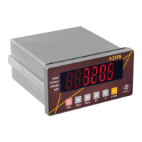
Details the front panel layout, status lights, and keys.
Details the rear panel layout and connectors.
Wiring diagrams for four-wire and six-wire load cells.
Instructions for installing the indicator in a control panel.
Flow diagram and description for setting parameters like decimal point, max capacity, min division, zero tracking, unstable detection.
Procedures for zero calibration and weight calibration.
Details display values and division/time for zero tracking.
Details display values and division/time for unstable detection.
Flowchart for zero calibration and weight calibration.
Procedure for performing zero calibration, with option to skip.
Procedure for performing weight calibration, with option to skip.
Interface for connecting multiple indicators to a host controller.
Details on twisted pair transmission wires and their quality.
Describes connection methods for RS-422 and RS-485 buses.
Explains FG grounding for RS-485 to improve anti-noise.
Specifies transmit format 1 with header, data, units, terminators.
Specifies transmit format 2 with initial code, data, unit, status, terminators.
Specifies transmit format 3 with header, data, unit, terminators.
Specifies transmit format 4 with header, data, unit, terminators.
Defines status codes: Stable, Unstable, Over Load.
Defines weight types: Gross, Net, Tare.
Describes the structure of the 8-digit weight data.
Pin assignment details for the Parallel BCD output interface.
Diagram showing DATA and OUT connections for the interface.
Specifies analogue current output, load resistor, and resolution.
Describes J1 short/open for voltage or current output selection.
Pin assignment for the parallel printer, RS-232, and current loop interface.
Details RS-232C (bi-directional) and CURRENT LOOP (one-way) operation.
Details RS-232C (bi-directional) and CURRENT LOOP (one-way) operation.
Configuration for data clock serial output.
Describes external input and relay output functions.
Defines pin functions for output: Zero Band, HI, OK, LO.
Diagram of the relay output circuit.
Diagram of the input circuit.
Procedure to reset all parameters to their default values.
Resets general function parameters to factory standards.
Procedure to enter and use the self-diagnosis mode.
Diagnoses the 7-digit display and LED status lights.
Diagnoses keyboard and calibration switch functionality.
Diagnoses RS-232 interface for output/input.
Diagnoses the BCD parallel output interface.
Diagnoses the analogue current output interface.
Diagnoses the parallel printer interface.
Diagnoses the main board EEPROM memory.
Diagnoses the OP-08 control I/O interface.
Table of general functions, parameters, descriptions, and defaults.
| Brand | Excell |
|---|---|
| Model | NC RACER EX-2001 |
| Category | Measuring Instruments |
| Language | English |