EX-2001 NC RACER ZSME300000091
11
EXCELL PRECISION CO., LTD.
6
1
2
8
7
5
4
3
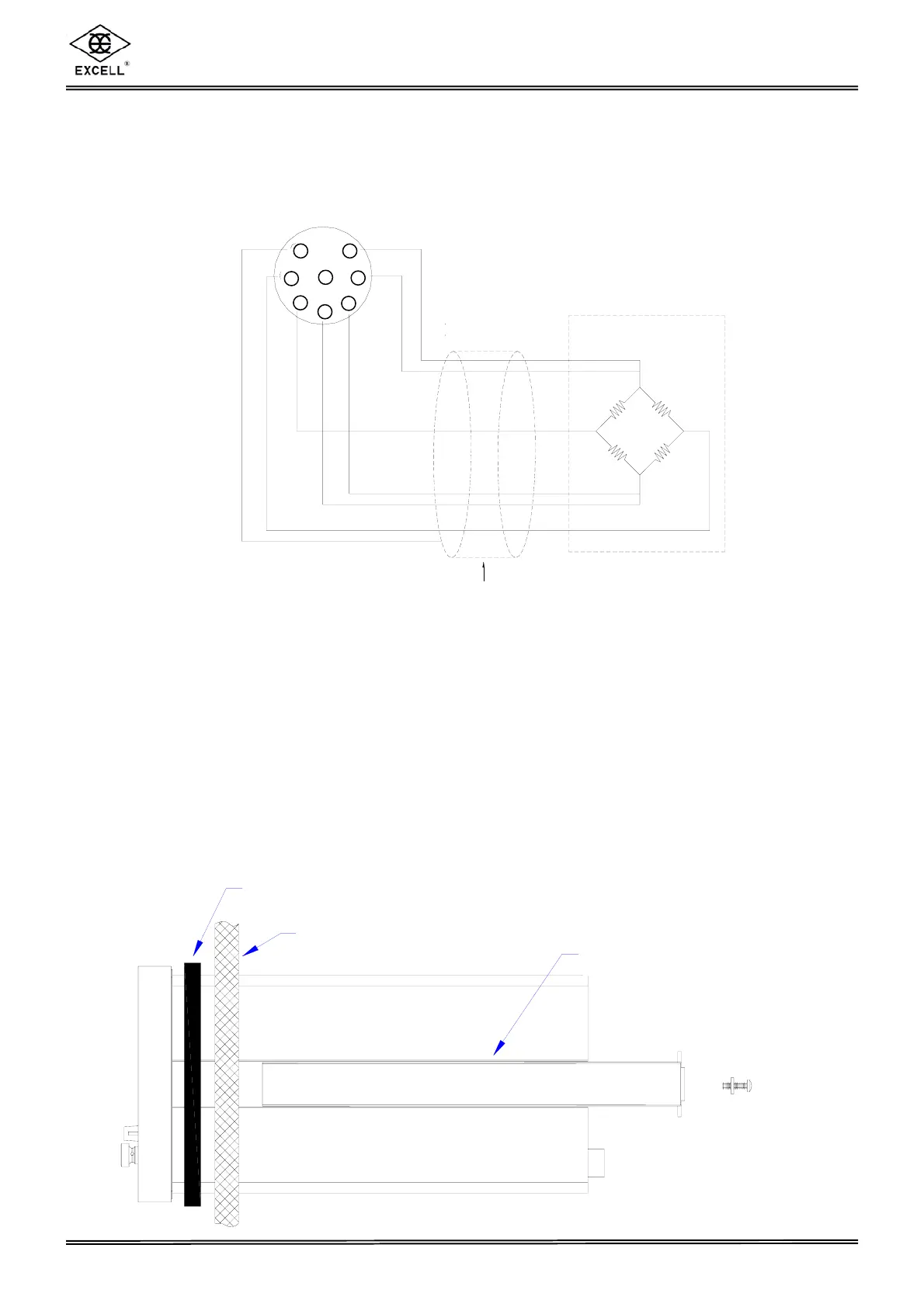
Load cell
Load cell cable
Shield
SEN+
SIG-SIG+
EXC+
EXC-
SEN-
CHAPTER 4 INSTALLATION
4-1 LOAD CELL
Four-wire (five-wire) load cell Six-wire (seven-wire) load cell
Pin 1 & 2 short, connected to EXC+ Pin 1 connected to EXC+
Pin 3 & 4 short, connected to EXC- Pin 2 connected to SEN+
Pin 5 connected to SIG+ Pin 3 connected to EXC-
Pin 6 connected to SIG- Pin 4 connected to SEN-
Pin 7 connected to the Shield Pin 5 connected to SIG+
Pin 6 connected to SIG-
Pin 7 connected to the Shield
4-2 INDICATOR INSTALLATION AND DIMENSIONS
2 The indicator can be installed in a control panel as detailed below
Packing
Panel
Fixed Rail
Load Cell
Load Cell Cable
Shield
1
2
3
4
5
6
7
8
 Loading...