Maintenance
Figure13
1.Positive(+)cableondischargedbattery
2.Positive(+)cableonboosterbattery
3.Negative(–)cableontheboosterbattery
4.Negative(–)cableontheengineblock
5.Boosterbattery
6.Dischargedbattery
7.Engineblock
4.Connecttheotherendofthepositivecabletothe
positiveterminaloftheboosterbattery.
5.Connecttheblacknegative(–)cabletotheother
terminal(negative)oftheboosterbattery.
6.MAKETHEFINALCONNECTIONON
THEENGINEBLOCKOFTHESTALLED
VEHICLE(NOTTOTHENEGATIVEPOST)
AWAYFROMTHEBATTERY .STANDBACK.
7.Startthevehicleandremovethecablesinthe
reverseorderofconnection(theengineblock
(black)connectionisthersttodisconnect).
CheckMowerBlades
ServiceInterval:Beforeeachuseordaily
1.Stopengine,waitforallmovingpartstostop,and
removekey.Engageparkingbrake.
2.Liftdeckandsecureinraisedpositionasstated
intheCleanGrassBuild-UpUnderDeck
procedure.
3.Inspectbladesandsharpenorreplaceasrequired.
4.Reinstalltheblades(iftheywereremoved)inthe
followingorder:
A.Installbushingthroughbladewithbushing
angeonbottom(grass)sideofblade.
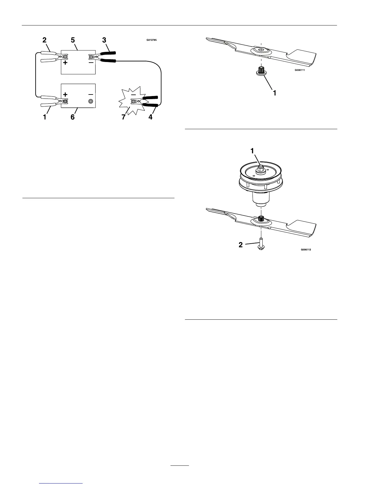
Figure14
1.Installbushinginbladepriortoinstallingbushingin
spindle.
B.Installbushing/bladeassemblyintospindle.
Figure15
1.Usewrenchherefor
bladeinstallation.This
nuthasbeentorquedto
90–110ft-lb(122–149
N-m)
2.Torqueto55-60ft-lb
(75-81N-m)Apply
lubricanttothreads
asneededtoprevent
seizing.Copper-based
anti-seizepreferable.
Greaseacceptable
substitute.
C.Applylubricanttothreadsofbladeboltas
neededtopreventseizing.Copper-based
anti-seizepreferable.Greaseacceptable
substitute.Installbladeboltngertight.Place
wrenchonthetopspindlenutthentorquethe
bladeboltsto55-60ft-lb(75-81N-m).
32
 Loading...