Maintenance
thechainboltsinthedeckliftarmsmakingsure
theydon’tmovewhiletightening.
9.Loosenthefournutswhichsecurethefront
swivels(twoperside)untilthefrontchainsare
looseandfrontofdeckissupportedbythe3/4
inch(19mm)block.DoNotloosenthefront
chainhardware.
10.Onleftside,adjustfrontswivelusingthelocking
nutbehindtheswiveluntilthefrontchainistight
andallslackisremovedfromlinkage.DoNotlift
frontofdeckoff3/4inch(19mm)block.Secure
frontswivelusinglockingnutinfrontofswivel.
Repeatforrightside.
11.Recheckthatthe3/4inch(19mm)blockstjust
snuglyunderthebracketsandthatthetensionon
allthechainsisapproximatelyequal.Makesure
allchainattachmentboltsaretight.Reposition
anti-scalprollersandtightensecurely.
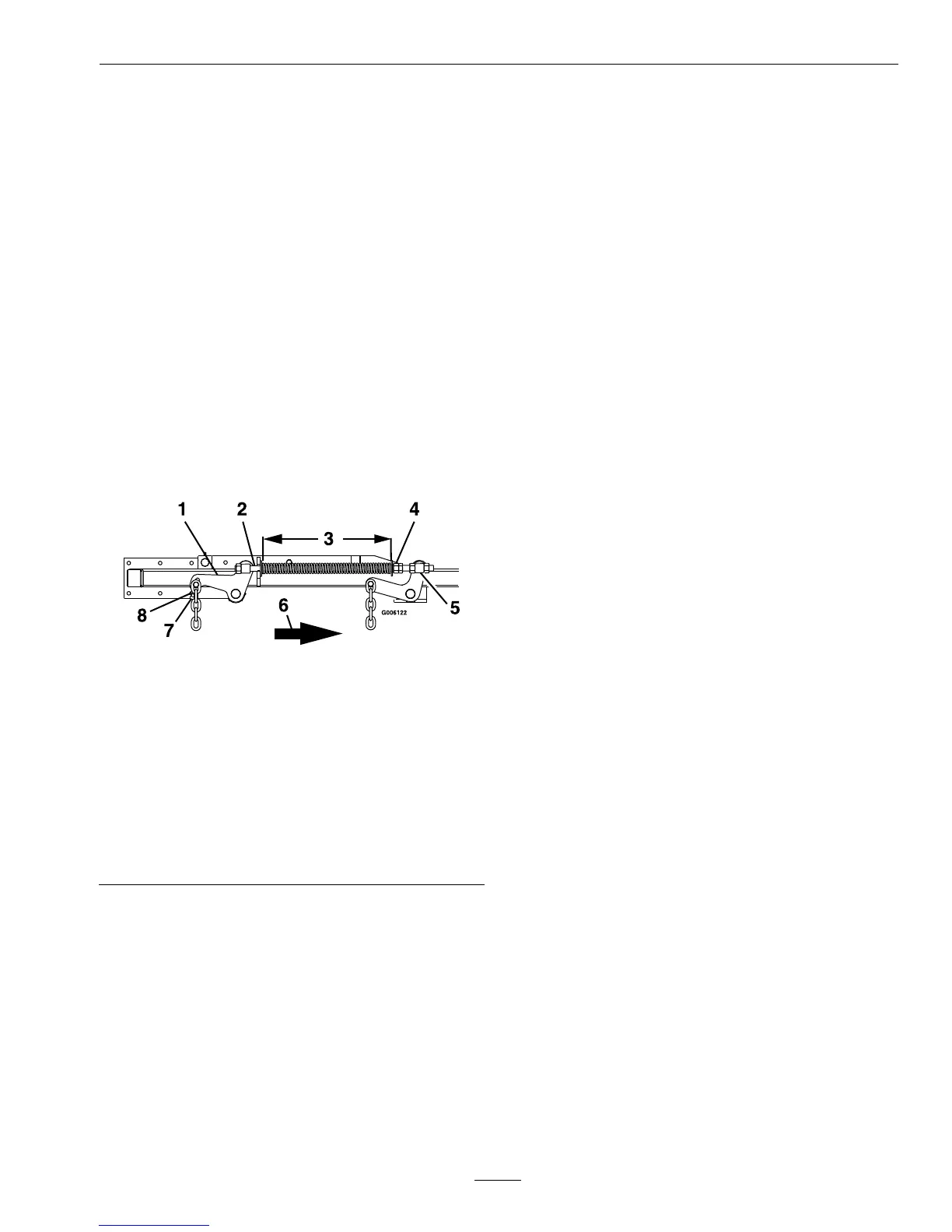
Figure18
1.Applydownwardpressurehere
2.Placelockingpliersheretoholdspring
3.13–1/2inches(34.3cm)forcutheightsat2inchesor
aboveor14inches(35.6cm)forcutheightsbelow2
inches
4.Removeforceondeckspringsbylooseningnutshere
5.Swivel
6.Frontofunit
7.Socketheadadjustingscrew
8.Jamnut
12.Raisedeckliftlevertothe5inch(12.7cm)
cuttingheightposition(Figure10).Adjustspring
compressionuntilproperdistanceisobtained
betweenthetwolargewashers(Figure18).
Adjustmentismadebyturningthenutatthe
frontofeachspring(clockwisewillshortenthe
spring,counterclockwisewilllengthenthespring).
Lockinpositionwithjamnuts.
Note:Whenaboveadjustmentshavebeenmade,
thefrontofthedeckwillbeslightlylowerthanthe
rearofthedeck.
PumpDriveBeltTension
Self-tensioning-Noadjustmentnecessary.
DeckBeltTension
Self-tensioning-Noadjustmentnecessary.
MuleDriveBeltTension
Adjustment
Self-tensioningidler,adjustasfollows:
1.Stopengine,waitforallmovingpartstostop,and
removekey.Engageparkingbrake.
2.Checktomakesurethecenterofthebolthead
inthecenterofthespringloadedpulley,onleft
sideenginedecksupport,ispositionedbetween
thecentersofthetwoalignmentholesinthe
leftsupportplate(
Figure19andFigure20).It
isnecessarytoadjustthebelttensionwhenthe
centeroftheboltheadisatorbelowthecenterof
thebottomalignmenthole.
3.Whenadjustmentisnecessary,loosentheidler
pulleyontheright-handsidesoitcanmoveup
anddownintheslot.
Placeawrenchonthe3/8inchnutinthecenter
ofthespringloadedpulleyandapplyupward
pressuretorelievetensiononthespring(a1/2
inchdrivebreakerbarand9/16inchsocketworks
best).
Repositiontheadjustingpulleytothebottomof
theslot.
Note:Wheninstallinganewbelt,itisnecessary
torepositiontherightadjustingpulleyupwardin
theslotinordertopositionthecenterofthespring
loadedpulleybetweenthealignmentholes.
41
 Loading...