Maintenance
CAUTION
Raisingthemowerdeckforserviceor
maintenancerelyingsolelyonmechanical
orhydraulicjackscouldbedangerous.The
mechanicalorhydraulicjacksmaynotbeenough
supportormaymalfunctionallowingtheunitto
fall,whichcouldcauseinjury.
DoNotrelysolelyonmechanicalorhydraulic
jacksforsupport.Useadequatejackstandsor
equivalentsupport.
1.Thisadjustmentmustbemadewiththedrive
wheelsturning.Firstraisetherearofmachine
upandsupportwithjackstands(orequivalent
support)justhighenoughtoallowthedrive
wheelstorotatefreely.
2.Unhookseatlatchandtiltseatforward.
3.Removetheelectricalconnectionfromtheseat
safetyswitch,locateddirectlytotheleftoftheseat
switchassemblybesidethehydraulicoilreservoir.
Temporarilyinstallajumperwireacrossthe
terminalsintheconnectorofthemainwiring
harness.
4.Runtheunitatleast5minuteswiththedrive
leversatfullforwardspeedtobringhydraulic
systemoiluptooperatingtemperature.
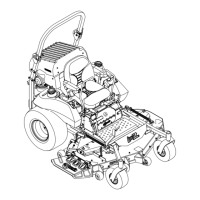
5.Loosenlocknutsfromtheballjointsateachend
ofthepumpcontrollinkage(
Figure28).
Figure28
Right-HandSideofUnit
1.Turnheretoadjust
2.Loosenhere(right-hand
thread)
6.Startengine.Brakemustbeengagedand
motioncontrolleversouttostartengine.
Operatordoesnothavetobeintheseat
becauseofthejumperwirebeingused.Run
engineatfullthrottleandreleasebrake.
7.Thereverseindicatorspringmustbecorrect
beforethefollowingadjustmentscanbemade.
SeetheReverseIndicatorAdjustmentsection.
Note:Themotioncontrolleverneedstobein
neutralwhilemakinganynecessaryadjustments.
Theleftrodassemblycontrolstheleftwheeland
therightrodassemblycontrolstherightwheel.
8.Bringthemotioncontrolleverintotheneutral
position.AdjustRHpumpcontrolrodlength
byrotatingthedoublenutsontherodinthe
appropriatedirectionuntilthewheelsslightly
creepinreverse(
Figure28).Movethemotion
controllevertothereversepositionandwhile
applyingslightpressuretotheleverallowthe
reverseindicatorspringtobringtheleversbackto
neutral.Thewheelmuststopturningorslightly
creepinreverse.Whenadjustmentiscomplete,
tightenlocknutsontoballjoints.
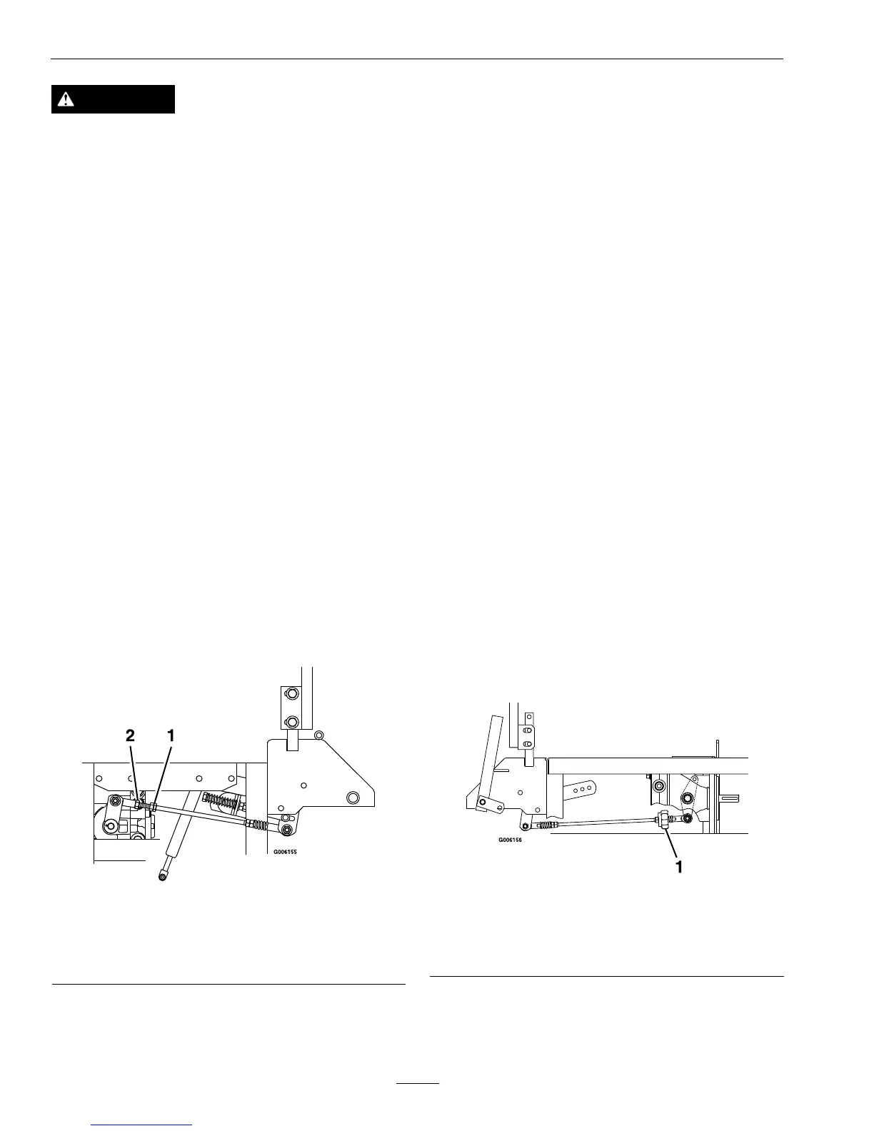
9.BringtheLHmotioncontrolleverintothe
neutralposition.AdjusttheLHpumpcontrolrod
lengthbyrotatingthetrackingadjustmentknobin
theappropriatedirectionuntilthewheelsslightly
creepinreverse.Movethemotioncontrollever
tothereversepositionandwhileapplyingslight
pressuretotheleverallowthereverseindicator
springtobringtheleversbacktoneutral.The
wheelmuststopturningorslightlycreepin
reverse(
Figure29).
Figure29
Left-HandSideofUnit
1.TurnLHtrackingadjustmentknob.(DoNotloosenany
nutsonLHside)
10.Shutoffunit.Removejumperwirefromwire
harnessconnectorandplugconnectorintoseat
switch.
46
 Loading...