Operation
g014657
Figure10
Toturnleftorright,releasepressureonthe
motioncontrollevertowardthedesiredturn
direction.
3.Tostop,positionbothmotioncontrolleversin
theneutraloperateposition.
AdjustingtheFrontReferenceBar
1.Inserta7/32inchallenwrenchthroughthehole
ononesideofthecontroltowerpanel.Place
a9/16inchwrenchonthecorrespondingnut
locatedunderneaththecontroltower.Loosenthe
boltandrepeatfortheoppositesideofthefront
referencebar(seeFigure8).
2.Rotatethebarforwardorrearward,limitingthe
forwardtravelofthecontrolleversuntildesired
maximumforwardspeedisachieved.
3.Tightenboltstolockreferencebarinplace.
AdjustingtheCuttingHeight
WARNING
Whenthetwofrontsupportrodhairpinsare
removedfromthemowerdeck,theweightofthe
tractorsectionmaycausethefrontframeofthe
machinetorisesuddenly.Ifthemachinerises
suddenly,injurymayoccur.
Securelyholddownthefrontofthemachine
whenraisingthemowerdeckforhairpin
repositioning.
Thecuttingheightofthemowerdeckisadjusted
from1to5inches(25mmto127mm)in1/2inch
increments.
Note:Mowingforextendedperiodsoftimeat1
inchheightofcutmayresultinreduceddeckbeltlife
duetoincreasedbeltoperatingangle.
1.Stopthemachineandmovethedriveleverstothe
neutrallockedposition.
2.DisengagethePTO.
3.Engagetheparkbrake.
4.Stoptheengine,removethekeyandwaitforall
movingpartstostop.
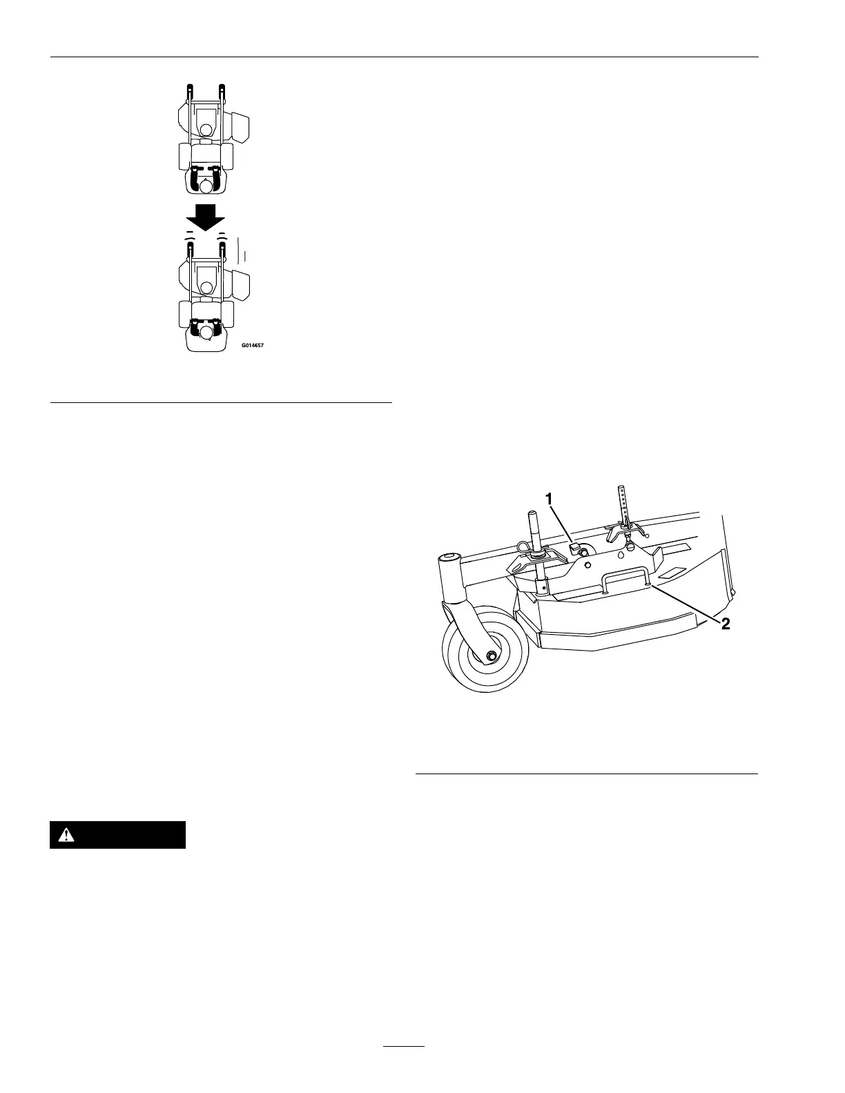
5.Liftthecuttingdeckusingthehandleasshownin
Figure11(handlepositionvarieswithdecksize)
tothehighestpositionpossible.Engagedeck
heightchangeassistleverbyrotatingforwarduntil
contactwiththedecksupportrod(seeFigure11).
Whiletheleverismanuallyengaged,lowerthe
decktorestonthelever.
g303934
Figure11
1.Deckheightchange
assistlever
2.Handle
6.Installhairpinclipsintheholesforthedesired
cuttingheight.SeeFigure12.
Important:Tomaintaincorrectcutting
heightandrake,checkthefollowingfor
properadjustment.
A.Thefrontandrearhairpinsareinthesame
holeswiththeproperspacersunderthehair
pins.SeeFigure12.
Note:Alldeckpinshaveagrooveat
the3inch(76mm)cutheightforeaseof
identication.
22