Turntable control SmartTurn
Structure and function
Dok-ID:EXPERT-0003-EN-2011 15
Pos: 4.2 / S martT ur n/Sm artT urn- Neu- 02.2 011/ 4.1.1 Ger äteb eschr eib ung @ 2\mod_1296729895005_38.doc @ 25805
4.1.1 Device description
Sensor, Fig. 1
The sensor is equipped with:
A connection for the control unit.
One green LED and two yellow LEDs.
All three LEDs are illuminated when the sensor is connected to the
control unit.
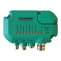
Control unit, Fig. 2
The controller is equipped with:
Four connections for 24 V supply and PLC signals (X1), power
unit (X2), sensor (X3), diagnostics connection (X4).
Eight LEDs that enable fast and easy diagnosis. Faults are
indicated through flashing red LEDs. More information about
faults is provided in the section -> Faults.
LED Function Color
H1 System fault Red
H2 Overrun forward Red
H3 0-position Yellow
H4 Overrun backward Red
H5 End lock angle Red
H6 Start forward on Yellow
H7 Start backward on Yellow
H8 Not assigned -
H9 24 V power supply Green
More extensive diagnoses is possible with the diagnostics
software, via the diagnostics connection (X4).
Pos: 4.3 / S martT ur n/Sm artT urn- Neu- 02.2 011 /4. 2 Fu nkti on sbes chr ei bung @ 2 \mod_1296730371811_38.doc @ 258 22